MODULAR SAFETY INTEGRATED CONTROLLER MOSAIC
8540780 • 10/07/2020 • Rev.38 203
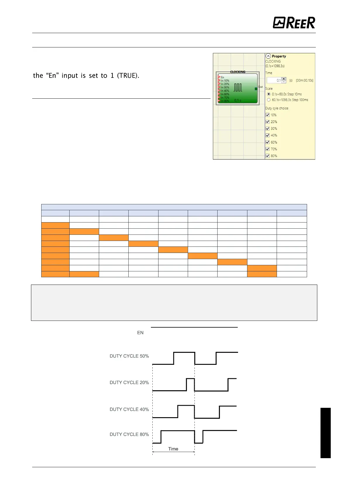
CLOCKING
The CLOCKING operator generates a square wave output
which period is set by the user. The output is enabled if
Clocking has up to 7
inputs to control output Duty Cycle.
Parameters
Time: The period can be set to between 100 ms and
1098,3 s.
Scale: The user can choose two different scales for the
time T to be set.
100 ms...60 s, step 10 ms
60,1 s...1098,3 s, step 100 ms
Duty cycle selection: Up to 7 inputs can be selected for 7 different output signal duty
cycles. Depending on the active input, the OUT clock signal has its corresponding duty
cycle. EN input must always be to 1 (TRUE).
Refer to the table below for all possible values of Duty cycle selectable by the user.
The circuit upstream clocking operator must ensure the presence of only one input
signal in addition to enable EN (excluded the pair 10% 80%).
The presence on EN input of high level (TRUE), generates an output signal with a duty
cycle = 50%.

 Loading...


