Home
Reer
Controller
MOSAIC MI8O4C
Reer MOSAIC MI8O4C Installation And Use
4
of 1
of 1 rating
239 pages
Give review
Manual
Specs
To Next Page
To Next Page
To Previous Page
To Previous Page
Loading...
MODULAR SAFE
TY INTE
GRATED CON
TROLLER
MOSAIC
8540780 • 10/07/2020 •
Rev.38
69
E
n
g
l
i
s
h
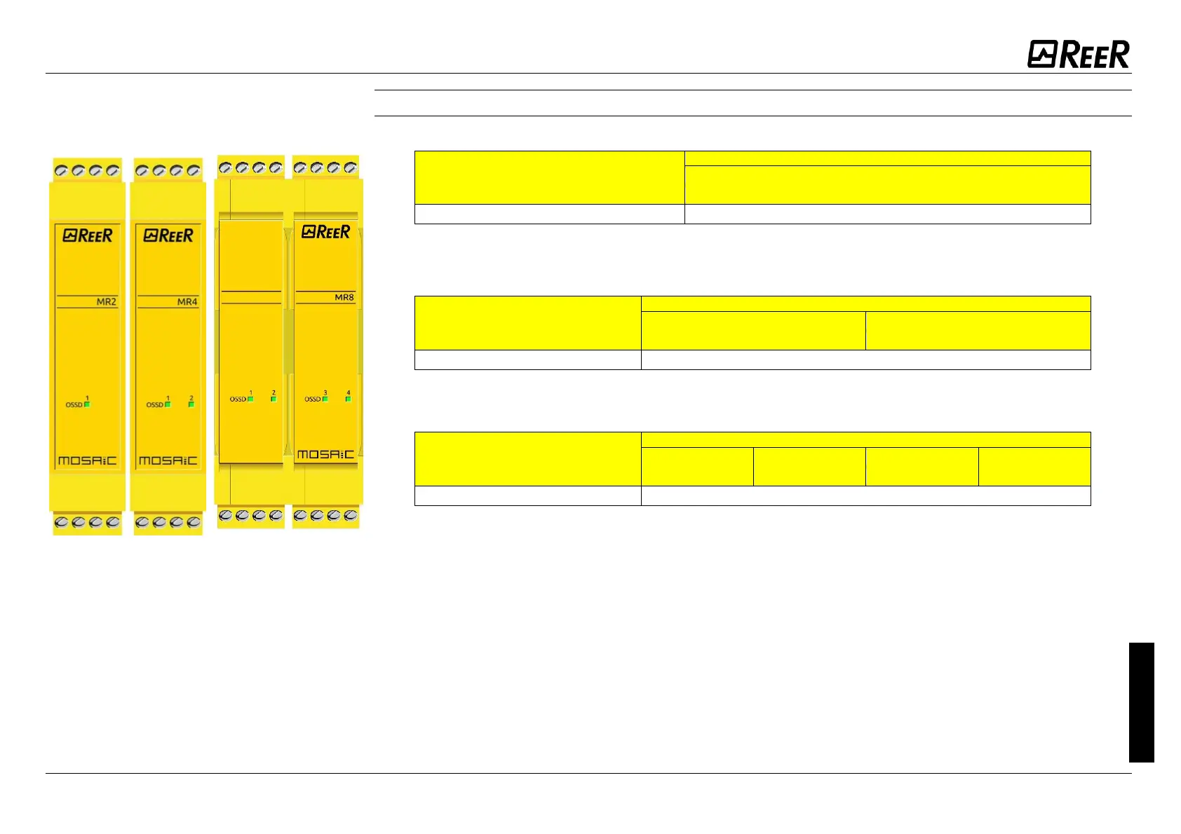
MR2, MR4,
MR8
(F
i
gur
e
31
)
MEAN
I
NG
LED
OSSD1
GREEN
NORM
AL
OPER
ATION
ON
with
output
activated
Table
57
-
MR2 - D
yn
am
ic sc
ree
n
MEAN
I
NG
LED
OSSD1
OSSD2
GREEN
GREEN
NORM
AL
OPER
ATION
ON
with o
utput
activated
Table
58
-
MR4 - D
yn
am
ic s
cr
een
MEAN
I
NG
LED
OSSD1
OSSD2
OSSD3
OSSD4
GREEN
GREEN
GREEN
GREEN
NORM
AL
OPER
ATION
ON
with o
utput
activated
Table
59
–
MR8 - D
yn
am
ic s
cr
een
Figu
re
31
- MR2
, MR4, M
R8
68
70
Table of Contents
Default Chapter
2
Table of Contents
2
Introduction
8
Contents of this Handbook
8
Important Safety Instructions
8
Abbreviations and Symbols
9
Applicable Standards
9
Overview
10
Product Composition
13
Installation
14
Mechanical Fastening
14
Calculation of Safety Distance of an ESPE Connected to MOSAIC
15
Electrical Connections
15
Instructions Concerning Connection Cables
16
Master Module M1
16
Master Module M1S
17
USB Input
18
MOSAIC Configuration Memory (MCM)
18
MULTIPLE LOAD Function
18
RESTORE Function
19
Module MI8O2
19
Module MI8O4
20
Module MI8
20
Module MI12T8
21
Module MI16
21
Module MO2
22
Module MO4
22
Module MO4L
23
Module MR2
24
Module MR4
24
Module MR8
25
Modules MV0 - MV1 - MV2
26
Encoder Connections with Rj45 Connector (Mv1, Mv2)
27
Module MOR4
28
Module MOR4S8
28
Module MOS8
29
Module MOS16
29
Module MO4LHCS8
30
Modulo MA2
30
Modulo MA4
31
MA2 / MA4 Analog Sensor Connections
32
Example of Connection of Mosaic to the Machine Control System
33
Checklist after Installation
33
Operating Diagram
34
Signals
35
Inputs
35
Master Enable
35
Node Sel
35
Proximity Input for Speed Controller MV
36
Configuration with Interleaved Proximity
36
Restart_Fbk
37
Outputs
38
OUT STATUS (SIL 1/PL C)
38
Out Test
38
Ossd Safety Outputs
38
Important Note Concerning Ossd Safety Outputs
38
Ossd (M1, Mi8O2, Mo2, Mo4)
39
Ossd (M1S, Mi8O4, Mo4L)
39
Ossd (Mo4Lhcs8)
41
Ossd Outputs Configuration
42
Safety Relays (Mr2, Mr4, Mor4, Mor4S8)
43
Characteristics of the Output Circuit
43
MR2/MR4/MR8 Internal Contacts Diagram
43
Example of MR2 Module Connection with Static OSSD Outputs of a Module M1
44
Switching Operation Timing Diagram
45
Technical Features
46
General System Characteristics
46
Safety Level Parameters
46
General Data
46
Enclosure
47
M1 Module
47
M1S Module
48
MI8O2 Module
48
MI8O4 Module
48
MI8 - MI16 Modules
49
MI12T8 Module
49
MO2 - MO4 Modules
49
MO4L Module
49
MOS8 MOS16 Modules
50
MR2 - MR4 MR8 Modules
50
MOR4 MOR4S8 Module
50
MO4LHCS8 Module
51
MV0 - MV1 - MV2 Modules
51
MA2, MA4 Module
52
Mechanical Dimensions
53
LED INDICATORS (Normal Operation)
54
Master M1 (Figure 16)
54
Master M1S (Figure 16)
55
MI8O2 (Figure 18)
56
MI8O4 (Figure 18)
57
MI8 (Figure 20)
58
MI12T8 (Figure 22)
59
MI16 (Figure 22)
60
MO2 (Figure 23)
61
MO4 (Figure 24)
62
MO4L (Figure 18)
63
MOR4 (Figure 26)
64
MOR4S8 (Figure 27)
65
MOS8 (Figure 28)
66
MOS16 (Figure 29)
67
MV0, MV1, MV2 (Figure 30)
68
MR2, MR4, MR8 (Figure 31)
69
MO4LHCS8 (Figure 32)
70
MA2, MA4 (Figure 33)
71
LED INDICATORS (Troubleshooting)
72
Master M1 (Figure 34)
72
Master M1S (Figure 35)
73
MI8O2 (Figure 36)
74
MI8O4 (Figure 37)
75
MI8 (Figure 38)
76
MI12T8 (Figure 39)
77
MI16 (Figure 40)
78
MO2 / MO4 (Figure 41)
79
MO4L (Figure 42)
80
MOR4 (Figure 43)
81
MOR4S8 (Figure 44)
82
MOS8 (Figure 45)
83
MOS16 (Figure 46)
84
MV0, MV1, MV2 (Figure 47)
85
MO4LHCS8 (Figure 48)
86
MA2, MA4 (Figure 49)
87
Mosaic Safety Designer Software
89
Installing the Software
89
PC HARDWARE Requirements
89
PC SOFTWARE Requirements
89
Installation of MSD Software
89
Fundamentals
90
Standard Tool Bar
91
Textual Tool Bar
92
Create a New Project (Configure the MOSAIC System)
92
EDIT CONFIGURATION (Composition of the Various Modules)
93
Change User Parameters
93
OBJECTS - OPERATOR - CONFIGURATION Tool Bars
94
Creating the Diagram
95
Use of Mouse Right Button
96
Example of a Project
97
Project Validation
97
Resources Allocation
98
Project Report
99
Connect to Mosaic
101
Sending the Configuration to the MOSAIC
101
Download a Configuration File (Project) from Mosaic
101
Configuration LOG
101
System Composition
102
Disconnecting System
102
MONITOR (I/O Status in Real Time - Textual)
103
MONITOR (I/O Status in Real Time - Textual - Graphic)
103
Password Protection
104
Level 1 Password
104
Level 2 Password
105
Password Change
105
TESTING the System
106
Object Function Blocks
107
Output Objects
107
OSSD (Safety Outputs)
107
SINGLE DOUBLE OSSD (Safety Output)
108
STATUS (SIL 1/PL C Output)
111
Fieldbus Probe
111
Relay
112
Use with RESTART: Automatic (A) or Manual (B) (Category 2)
113
Input Objects
115
E-STOP (Emergency Stop)
115
E-GATE (Safety Gate Device)
116
SINGLE E-GATE (Safety Gate Device)
117
Lock Feedback
118
ENABLE (Enable Key)
119
ESPE (Optoelectronic Safety Light Curtain / Laser Scanner)
120
FOOTSWITCH (Safety Pedal)
121
MOD-SEL (Safety Selector)
123
PHOTOCELL (Safety Photocell)
124
TWO-HAND (Bimanual Control)
125
Network_In
125
Sensor
126
S-MAT (Safety Mat)
127
Switch
128
Enabling Grip Switch
129
Testable Safety Device
130
Solid State Device
131
Fieldbus Input
132
Ll0-Ll1
133
Comments
133
Title
133
Speed Control Type Function Blocks
134
Warning Concerning Safety
134
Note Concerning Speed Control Functional Blocks
134
Speed Control
135
Window Speed Control
138
Stand Still
140
Stand Still and Speed Control
142
Analog Input Type Function Blocks
145
ANALOG INPUT (4 Inputs each MA4 Module, 2 Inputs each MA2 Module)
145
ANALOG DIVISION (4 Inputs each MA4 Module, 2 Inputs each MA2 Module)
158
Operator Function Blocks
171
Logical Operators
171
And
171
Nand
171
Not
172
Nor
172
Xor
173
Xnor
173
Logical Macro
174
Multiplexer
174
DIGITAL COMPARATOR (M1S Only)
175
Memory Operators
177
D FLIP FLOP (Max Number = 16 with M1, 32 with M1S)
177
T FLIP FLOP (Max Number = 16 with M1, 32 with M1S)
177
Sr Flip Flop
177
USER RESTART MANUAL (Max Number = 16 with M1, 32 with M1S with Other RESTART Operators)
178
USER RESTART MONITORED (Max Number = 16 with M1, 32 with M1S with Other RESTART Operators)
179
MACRO RESTART MANUAL (Max Number = 16 with M1, 32 with M1S with Other RESTART Operators)
179
MACRO RESTART MONITORED (Max Number = 16 with M1, 32 with M1S with Other RESTART Operators)
180
PRE-RESET (M1S Only) (Max Number = 32 with Other RESTART Operators)
181
GUARD LOCK OPERATORS (Max Number = 4 with M1, 8 with M1S)
182
Guard Lock
182
Counter Operators
194
COUNTER (Max Number = 16)
194
Counter Comparator
195
TIMER OPERATORS (Max Number = 32 with M1, 48 with M1S)
196
Monostable
196
Monostable_B
197
Passing Make Contact
198
Delay
199
Long Delay
200
Delay Comparator
201
Delay Line
201
Long Delay Line
202
Clocking
203
Muting Function
204
MUTING OPERATORS (Max Number = 4 with M1, 8 with M1S)
204
Concurrent" MUTING
204
Sequential" MUTING
206
MUTING OVERRIDE (Max Number = 4)
209
ANALOG OPERATORS (M1S Only)
211
Analog Comparator
211
Math (Max Number = 16)
214
Equality Check (Max Number = 16)
215
Miscellaneous Function Blocks
216
SERIAL OUTPUT (Max Number = 4 with M1, 8 with M1S)
216
NETWORK (Max Number = 1)
217
Example of Application in Category 2 According to ISO 13849-1
220
Logical Block Diagram of a Safety Function Using the Network
221
Example of Application in Category 4 According to ISO 13849-1
221
Logical Block Diagram of a Safety Function Using the Network
222
Reset M1
222
OSSD EDM (M1S Only, Max Number = 32)
222
Interpage In/Out
223
INTFBK_IN / INTFBK_OUT (M1S Only, Max Number = 8)
224
Terminator
224
Special Applications
225
Output Delay with Manual
225
Simulator Feature
226
Schematic Simulation
227
How to Use Graphic Simulation
229
Application Example of Graphic Simulation
232
Mosaic Fail Codes
234
Errors Log Download
235
Accessories and Spare Parts
236
Warranty
237
Other manuals for Reer MOSAIC MI8O4C
Installation And Use Manual
266 pages
Quick Installation Guide
20 pages
4
Based on 1 rating
Ask a question
Give review
Questions and Answers:
Need help?
Do you have a question about the Reer MOSAIC MI8O4C and is the answer not in the manual?
Ask a question
Reer MOSAIC MI8O4C Specifications
General
Brand
Reer
Model
MOSAIC MI8O4C
Category
Controller
Language
English
Related product manuals
Reer MOSAIC MI8O2
169 pages
Reer MOSAIC MI8
2 pages
Reer MOSAIC MI802
143 pages
Reer MOSAIC MI16
169 pages
Reer MOSAIC M1
266 pages
Reer MOSAIC MR4
169 pages
Reer MOSAIC M1S
266 pages
Reer MOSAIC MR2
169 pages
Reer Mosaic MOR4
169 pages

 Loading...


