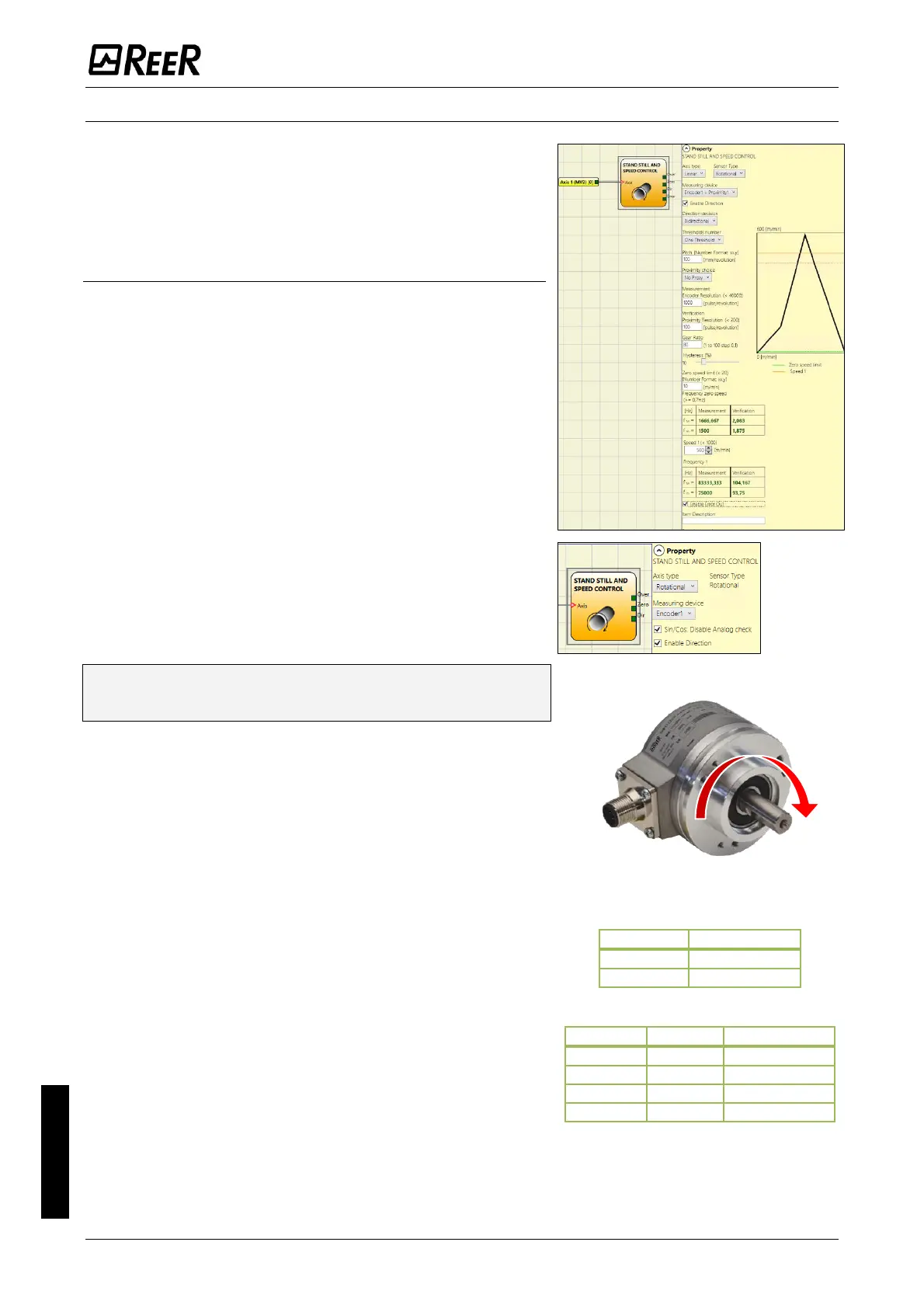
The StandStill and Speed Control function block monitors
the speed of a device, causing the transition from 0 (FALSE)
to 1 (TRUE) of the ZERO output when the speed is lower than
a selected output. In addition a transition from 0 (FALSE) to
1 (TRUE) of the OVER output is generated when the measured
speed exceeds a predetermined threshold.
Parameters
Axis type: It defines the type of axis controlled by the device.
It will be Linear in the case of a translation and will be
rotational in the case of motion around an axis.
Sensor Type: In the event that the previous parameter is
Linear, the Sensor Type defines the type of sensor connected
to the module inputs. It can be rotational (e.g. shaft encoder)
or Linear (e.g. optical array). This choice allows to define the
following parameters.
Measuring device: It defines the type of sensor(s) used. The
possible choices are:
- Encoder
- Proximity
- Encoder+Proximity
- Proximity1+ Proximity2
- Encoder1+ Encoder2
Sin/Cos: Disable Analog check: only when a Sin/Cos
Encoder is used, it is possible to disable the analog
verification sin
2
θ + cos
2
θ, carrying out a simplified plausibility
check of the Encoder signals.
Please note that when the analog check is disabled the
diagnostic coverage decreases.
Enable direction: (Available only when at least one Encoder
input is present): when checked, the DIR output is enabled on
the function block. This output will be 1 (TRUE) when the axis
rotates Counterclockwise and will be 0 (FALSE) when the axis
rotates Clockwise.
Direction decision: It defines the direction of rotation for
which the set thresholds are made active. The possible
choices are:
- Bidirectional
- Clockwise
- Counterclockwise
If Bidirectional is selected, the excess of the set threshold is
detected whether the axis rotates clockwise or
counterclockwise. Selecting Clockwise or Counterclockwise,
this is detected only when the axis rotates in the selected
direction.
Threshold number: It allows you to enter the number of
thresholds for the maximum value of speed. Changing this
value will increase/decrease the number of thresholds that
can be entered from a minimum of 1 to a maximum of 8 with
M1 fw >= 4.0, M1S fw >=5.1 and MVx fw >= 2.0 and 4 with
M1 fw <4.0 or o M1S fw< 5.1 or MVx fw < 2.0. In the case of
thresholds greater than 1, the input pins for the selection of
the specific threshold will appear in the lower part of the
function block. Let the user to choose which threshold has to
be enabled.

 Loading...


