MODULAR SAFETY INTEGRATED CONTROLLER MOSAIC
218 8540780 • 10/07/2020 • Rev.38
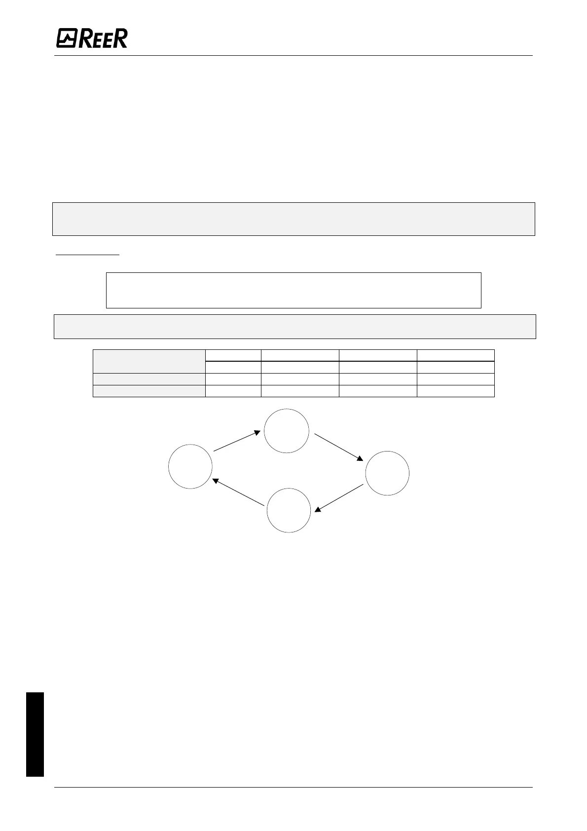
Condition 2:
With reference to the Figure 86 and Figure 87, when the emergency stop is pressed in one of the
four nodes:
1. The Net_out moves to condition 0 (FALSE);
2. The STOP signal is sent via the Net_out line;
3. The next node receives the stop code and deactivates the output;
4. The stop command generates the stop code for all Net_in and Net_out lines;
5. As the end result, the Net_out of all the connected nodes is in condition 0 (FALSE).
6. When the emergency stop is restored to the normal position, all the nodes can be restarted by sending the START signal
with a single reset. The latter condition does not occur when ENABLE RESET NETWORK is not enabled. In that case, the
local reset method must be used. The system will employ about 4s to restore all the outputs of the blocks that make up the
network.
Perform a local reset of the module which caused the network shutdown, to restore its
safety output.
Response Time
The max response time of the network starting from emergency stop is given by the formula:
(Master M1) t
r
= 11.3 ms + [175.3 ms x (number of controllers – 1)]
(Master M1S) t
r
= 12.7 ms + [232.7 ms x (number of controllers – 1)]
The max number of connected Master must be 10.
Condition 3:
With reference to the Figure 84 and Figure 85, when the IN input of the NETWORK function block of
one of the 4 nodes moves to condition 0 (FALSE):
1. The local OUTPUT moves to condition 0 (FALSE);
2. The RUN signal continues to be sent via the Network_out lines;
3. The states of the remaining nodes remain unchanged;
4. In that case, local reset must be used. The Reset-in LED flashes to indicate this condition. This condition is
signaled by the corresponding LED flashing Reset_In entrance.
The affected node will be restarted with its own reset (if 'Reset Global Reset' is not selected).
The Network_in input and the Network_out output can only be mapped to the I/O pins of the
MASTER.

 Loading...


