13. Timer S
puorG92/C61M
page 154
854fo7002,03.raM21.1.veR
2110-1010B90JER
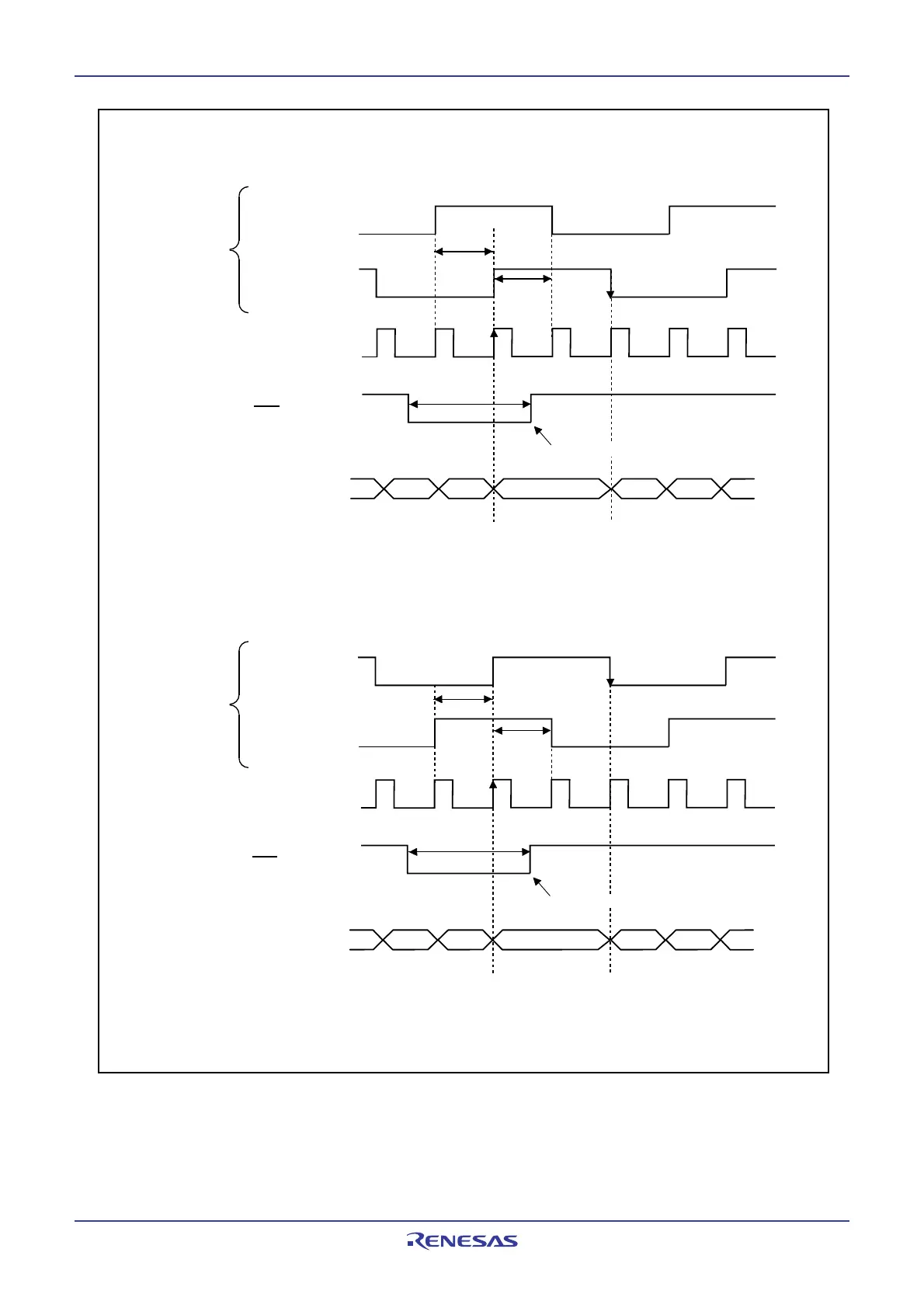
Figure 13.14 Base Timer Operation in Two-phase Pulse Signal Processing Mode
(1) When the base timer is reset while the base timer increments the counter
(2) When the base timer is reset while the base timer decrements the counter
( )
m
When selects no
division with the divider by (n+1)
Value of counter
min 1 µs
(Note 1)
min 1 µs
m+1 1 20
Set to 0 at this timing
Base timer starts counting
P8
0 (A-phase)
P8
1 (B-phase)
INT1 (Z-phase)
Set to 1 at this timing
min 1 µs
(1)
min 1 µs
m
Input waveform
Value of counter
m-1
FFFF
16 FFFE16
0
Set to 0 at this timing
NOTE:
1. 1.5 f
BT1 clock cycle or more are required.
Base timer starts counting
P8
0 (A-phase)
P8
1 (B-phase)
INT1 (Z-phase)
Set to FFFF16 at this timing
Input waveform
fBT1
fBT1
( )
When selects no
division with the divider by (n+1)
 Loading...


