13. Timer S
puorG92/C61M
page 153
854fo7002,03.raM21.1.veR
2110-1010B90JER
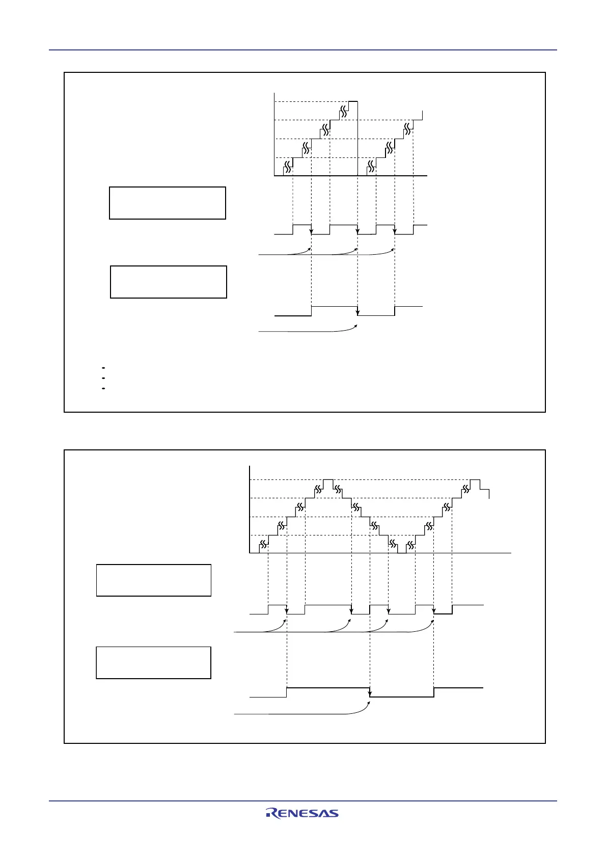
Figure 13.12 Counter Increment Mode
Figure 13.13 Counter Increment/Decrement Mode
FFFF
16
8000
16
0000
16
4000
16
C000
16
State of a counter
Base Timer interrupts
1
0
b14 overflow signal
1
0
b15 overflow signal
Base Timer interrupt
IT=0 in the G1BCR0 register
(Base timer interrupt generated
by the bit 15 overflow)
IT=1 in the G1BCR0 register
(Base timer interrupt generated
by the bit 14 overflow)
The above applies to the following conditions.
The RST4 bit in the G1BCR0 register is set to 0 (the base timer is not reset by matching the G1BTRR register)
The RST1 bit in the G1BCR1 register is set to 0 (the base timer is not reset by matching the G1PO0 register)
Bits UD1 to UD0 in the G1BCR1 register are set to 00
2
(counter increment mode)
FFFF
16
8000
16
4000
16
C000
16
0000
16
State of a counter
1
0
Base Timer interrupts
b14 overflow signal
1
0
b15 overflow signal
Base Timer interrupt
IT=0 in the G1BCR0 register
(Base timer interrupt generated
by the bit 15 overflow)
IT=1 in the G1BCR0 register
(Base timer interrupt generated
by the bit 14 overflow)
 Loading...


