14. Serial I/O
puorG92/C61M
page 202
854fo7002,03.raM21.1.veR
2110-1010B90JER
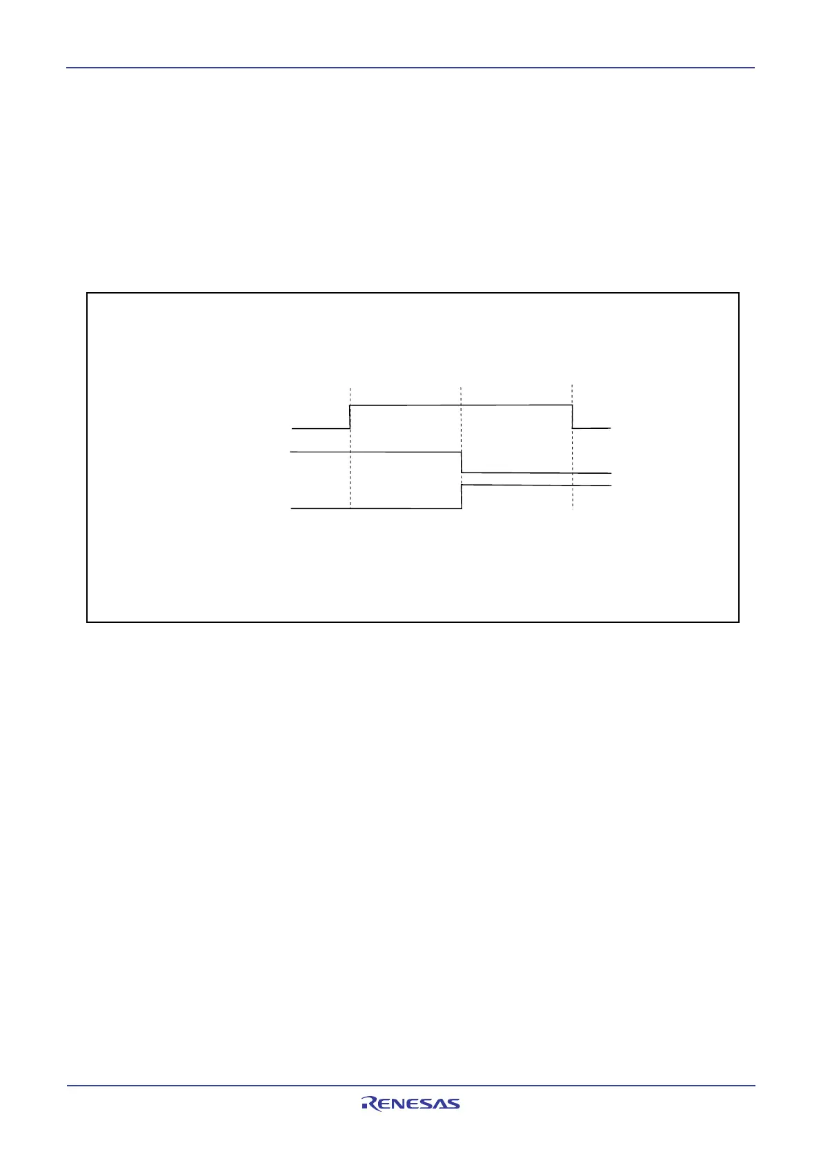
14.1.3.1 Detection of Start and Stop Condition
Whether a start or a stop condition has been detected is determined.
A start condition-detected interrupt request is generated when the SDA2 pin changes state from high
to low while the SCL2 pin is in the high state. A stop condition-detected interrupt request is generated
when the SDA2 pin changes state from low to high while the SCL2 pin is in the high state.
Because the start and stop condition-detected interrupts share the interrupt control register and vec-
tor, check the BBS bit in the U2SMR register to determine which interrupt source is requesting the
interrupt.
Figure 14.24 Detection of Start and Stop Condition
14.1.3.2 Output of Start and Stop Condition
A start condition is generated by setting the STAREQ bit in the U2SMR4 register to 1 (start).
A restart condition is generated by setting the RSTAREQ bit in the U2SMR4 register to 1 (start).
A stop condition is generated by setting the STPREQ bit in the U2SMR4 register to 1 (start).
The output procedure is described below.
(1) Set the STAREQ bit, RSTAREQ bit or STPREQ bit to 1 (start).
(2) Set the STSPSEL bit in the U2SMR4 register to 1 (output).
Make sure that no interrupts or DMA transfers will occur between (1) and (2).
The function of the STSPSEL bit is shown in Table 14.14 and Figure 14.25.
Setup time
Hold time
SCL2
SDA2
(
Start condition)
SDA2
(
Stop condition)
3 to 6 cycles < setup time
(1)
3 to 6 cycles < hold time
(1)
NOTE:
1. When the PCLK1 bit in the PCLKR register is set to 1, the cycles indicates the f1SIO's
generation frequency cycles; when PCLK1 bit is set to 0, the cycles indicated the
f2SIO's generation frequency cycles.
 Loading...


