20. Flash Memory Version
puorG92/C61M
page 343
854fo7002,03.raM21.1.veR
2110-1010B90JER
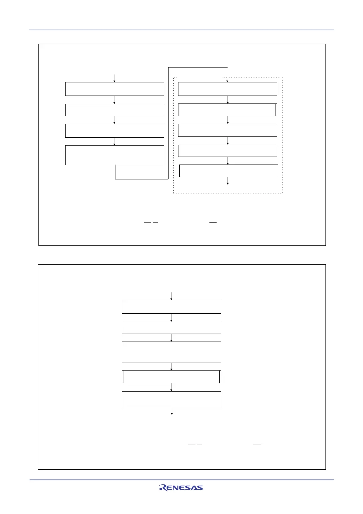
Figure 20.8 Setting and Resetting of EW Mode 0
Figure 20.9 Setting and Resetting of EW Mode 1
Execute the Read Array command
(3)
Single-chip mode
Set CM0, CM1, and PM1 registers
(1)
Execute software commands
Jump to the rewrite control program transfered to an
internal RAM area (in the following steps, use the
rewrite control program internal RAM area)
Transfer a rewrite control program to internal RAM
area
Write 0 to the FMR01 bit
(CPU rewrite mode disabled)
Set the FMR01 bit to 1 after writing 0 (CPU
rewrite mode enabled)
(2)
EW mode 0 operation procedure
Rewrite control program
Jump to a specified address in the flash memory
NOTES:
1. Select 10 MHz or below for CPU clock using the CM06 bit in the CM0 register and bits CM17 to 16 in the CM1
register. Also, set the PM17 bit in the PM1 register to 1 (with wait state).
2. Set the FMR01 bit to 1 immediately after setting it to 0. Do not generate an interrupt or a DMA transfer
between setting the bit to 0 and setting it to 1. Set the FMR01 bit in a space other than the internal flash
memory. Also, set only when the P8
5
/NMI/SD pin is “H” at the time of the NMI function selected.
3. Disables the CPU rewrite mode after executing the read array command.
Single-chip mode
Set CM0, CM1, and PM1 registers
(1)
Set the FMR01 bit to 1 (CPU rewrite mode
enabled) after writing 0
Set the FMR11 bit to 1 (EW mode 1) after writing
0
(2, 3)
Program in ROM
EW mode 1 operation procedure
Execute software commands
Set the FMR01 bit to 0
(CPU rewrite mode disabled)
NOTES:
1. Select 10 MHz or below for CPU clock using the CM06 bit in the CM0 register and bits CM17 to 16
in the CM1 register. Also, set the PM17 bit in the PM1 register to 1 (with wait state).
2. Set the FMR01 bits to 1 immediately after setting it to 0. Do not generate an interrupt or a DMA
transfer between setting the bit to 0 and setting the bit to 1. Set the FMR01 bit in a space other than
the internal flash memory. Set only when the P8
5
/NMI/SD pin is “H” at the time of the NMI function
selected.
3. Set the FMR11 bit to 1 immediately after setting it to 0 while the FMR01 bit is set to 1. Do not
generate an interrupt or a DMA transfer between setting the FMR11 bit to 0 and setting it to 1.
 Loading...


