7. Clock Generation Circuit
page 64
854fo7002,03.raM21.1.veR
2110-1010B90JER
puorG92/C61M
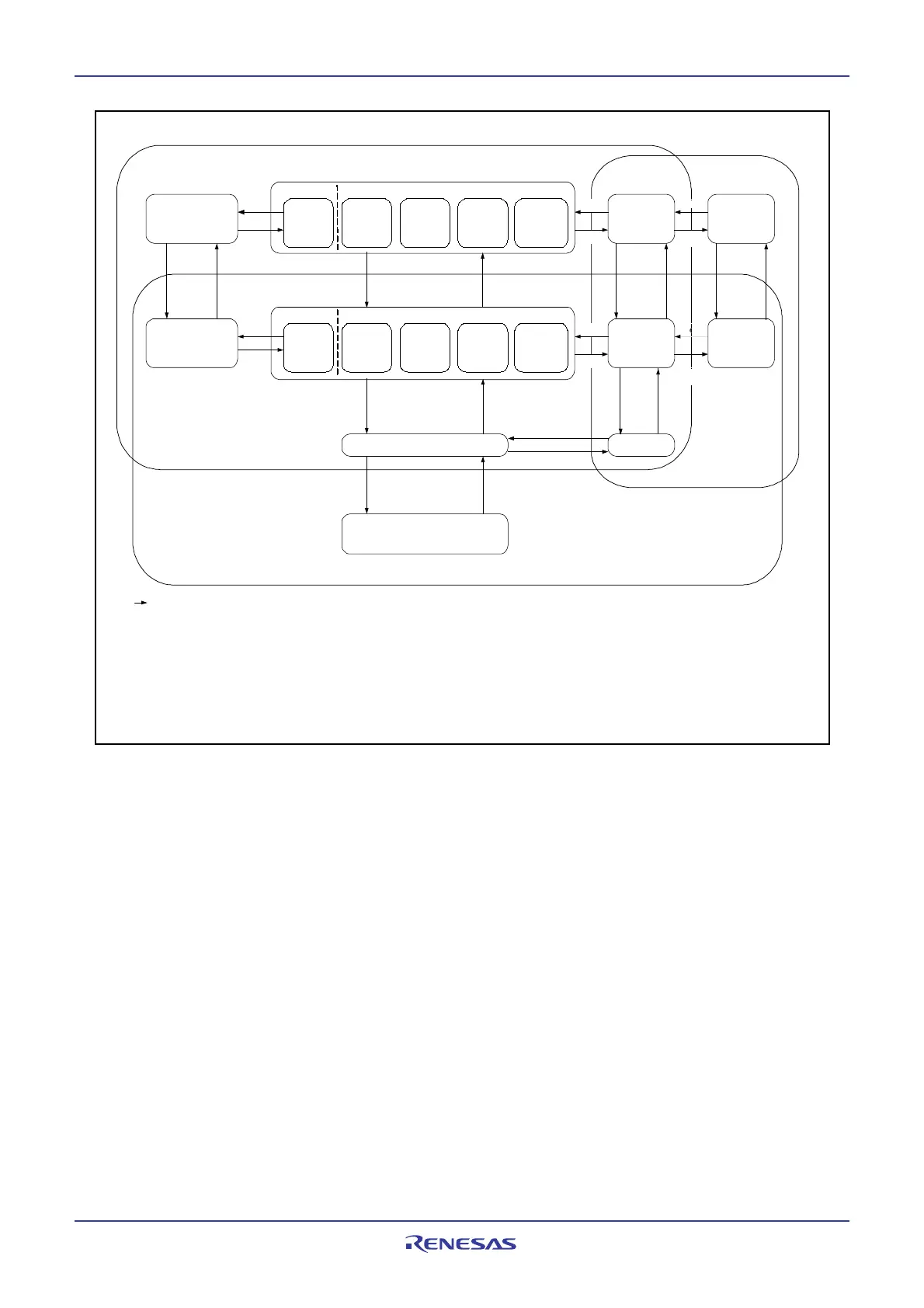
Figure 7.12 State Transition in Normal Mode
CM04=0
CPU clock: f(PLL)
CM07=0
CM06=0
CM17=0
CM16=0
PLL operation mode
CM07=0
CM06=0
CM17=0
CM16=0
CM07=0
CM17=0
CM06=0
CM16=0
CM07=0
CM17=0
CM06=0
CM16=1
CM07=0
CM17=1
CM06=0
CM16=0
CM07=0
CM06=1
CM07=0
CM17=1
CM06=0
CM16=1
High-speed mode
CM07=0
CM17=0
CM06=0
CM16=0
CM07=0
CM17=0
CM06=0
CM16=1
CM07=0
CM17=1
CM06=0
CM16=0
CM07=0
CM06=1
CM07=0
CM17=1
CM06=0
CM16=1
CM07=0
Low-speed mode
CM07=0
Low power dissipation mode
CM06=1
CM15=1
On-chip oscillator mode
CPU clock
On-chip oscillator
mode
CPU clock
CPU clock
On-chip oscillator
low power
dissipation mode
CPU clock
CM07=0
Low-speed
mode
PLC07=1
CM11=1
(5)
PLC07=0
CM11=0
(5)
CM04=0
PLC07=1
CM11=1
PLC07=0
CM11=0
CM04=0CM04=1CM04=1 CM04=1 CM04=0CM04=1
CM07=0
(2, 4)
CM07=1
(3)
CM05=1
(1, 7)
CM05=0
CM21=0
(2, 6)
CM21=1
CM21=0
(2, 6)
CM21=1
CM21=0
CM21=1
Main clock oscillation
On-chip oscillator clock
oscillation
Sub clock oscillation
f(ROC)
f(ROC)/2
f(ROC)/4
f(ROC)/8
f(ROC)/16
f(ROC)
f(ROC)/2
f(ROC)/4
f(ROC)/8
f(ROC)/16
f(ROC)
f(ROC)/2
f(ROC)/4
f(ROC)/8
f(ROC)/16
f(ROC)
f(ROC)/2
f(ROC)/4
f(ROC)/8
f(ROC)/16
PLL operation
mode
CPU clock: f(PLL)
CPU clock: f(XIN)
High-speed mode
Middle-speed mode
(divide by 2)
CPU clock: f(X
IN
)/2
CPU clock: f(X
IN
)/4 CPU clock: f(X
IN
)/8 CPU clock: f(X
IN
)/16
CPU clock: f(XCIN)
CPU clock: f(X
CIN)
CPU clock: f(X
CIN)
CM05=1
(1)
CM05=1
(1)
CM05=0
(5)
(5)
Middle-speed mode
(divide by 4)
Middle-speed mode
(divide by 8)
Middle-speed mode
(divide by 16)
Middle-speed mode
(divide by 2)
Middle-speed mode
(divide by 4)
Middle-speed mode
(divide by 8)
Middle-speed mode
(divide by 16)
CPU clock: f(XIN)
CPU clock: f(X
IN
)/2
CPU clock: f(X
IN
)/4
CPU clock: f(X
IN
)/8 CPU clock: f(X
IN
)/16
On-chip oscillator low power
dissipation mode
: Arrow shows mode can be changed. Do not change mode to another mode when no arrow is shown.
NOTES:
1. Avoid making a transition when the CM20 bit is set to 1 (oscillation stop, re-oscillation detection function enabled).
Set the CM20 bit to 0 (oscillation stop, re-oscillation detection function disabled) before transiting.
2. Wait for the main clock oscillation stabilization time before switching over. Set the CM15 bit in the CM1 register to 1 (drive capacity High) until main clock oscillation is stabilized.
3. Switch clock after oscillation of sub-clock is sufficiently stable.
4. Change bits CM17 and CM16 before changing the CM06 bit.
5. The PM20 bit in the PM2 register becomes effective when the PLC07 bit in the PLC0 register is set to 1 (PLL on). Change the PM20 bit when the PLC07 bit is set to 0 (PLL off).
Set the PM20 bit to 0 (2 waits) when PLL clock > 16MHz.
6. Set the CM06 bit to 1 (division by 8 mode) before changing back the operation mode from on-chip oscillator mode to high- or middle-speed mode.
7. When the CM21 bit is set to 0 (on-chip oscillator turned off) and the CM05 bit is set to 1 (main clock turned off), the CM06 bit is fixed to 1 (divide-by-8 mode) and the
CM15 bit is fixed to 1 (drive capability High).
CM07=1
(3)
CM07=0
(4)
 Loading...


