7. Clock Generation Circuit
page 65
854fo7002,03.raM21.1.veR
2110-1010B90JER
puorG92/C61M
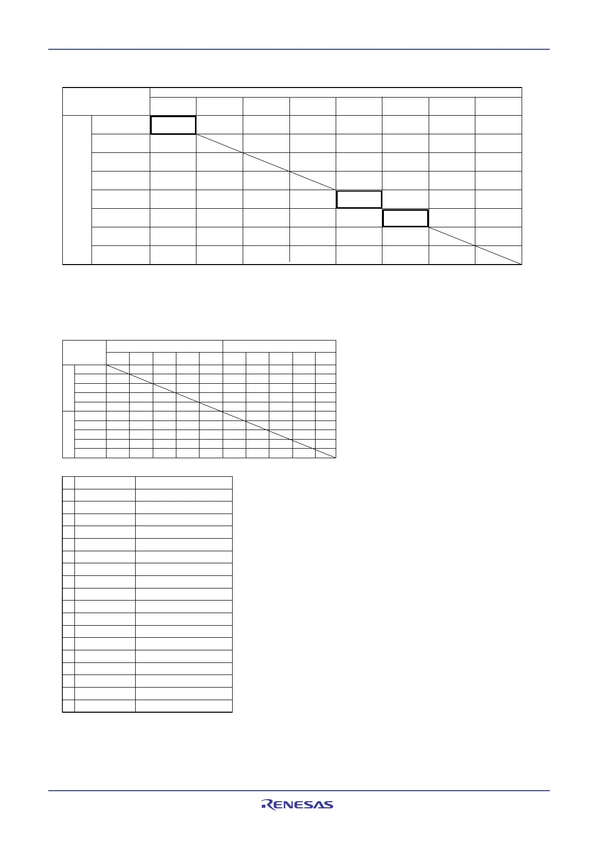
Table 7.7 Allowed Transition and Setting
High-speed mode,
middle-speed mode
On-chip oscillator mode
Stop mode
Wait mode
On-chip oscillator
low power dissipation
mode
PLL operation mode
2
Low power dissipation
mode
Low-speed mode
2
Current state
State after transition
8
--
(8)
(18)
5
(9)
7
--
(10)
(11)
1, 6
(12)
3
(14)
4
--
-- --
--
(13)
3
(15) --
--
--
--
--
--
(10)
--
--
--
-- -- --
--
--
(18)(18) --
--
(16)
1
(17)
(16)
1
(17)
(16)
1
(17)
(16)
1
(17)
(16)
1
(17)
--
--
(18)
5
(18)
5
(18)(18)(18)(18)(18)
(1)
(2)
(3)
(4)
(5)
(6)
(7)
(8)
(9)
(10)
(11)
(12)
(13)
(14)
(15)
(16)
(17)
(18)
Setting Operation
CM04 = 0 Sub clock turned off
CM04 = 1 Sub clock oscillating
CM06 = 0,
CPU clock no division mode
CM17 = 0 , CM16 = 0
CM06 = 0,
CPU clock division by 2 mode
CM17 = 0 , CM16 = 1
CM06 = 0,
CPU clock division by 4 mode
CM17 = 1 , CM16 = 0
CM06 = 1
CPU clock division by 8 mode
CM06 = 0,
CPU clock division by 16 mode
CM17 = 1 , CM16 = 1
CM07 = 0
Main clock, PLL clock,
or on-chip oscillator clock selected
CM07 = 1 Sub clock selected
CM05 = 0 Main clock oscillating
CM05 = 1 Main clock turned off
PLC07 = 0,
CM11 = 0
Main clock selected
PLC07 = 1,
CM11 = 1
PLL clock selected
CM21 = 0
Main clock or PLL clock selected
CM21 = 1 On-chip oscillator clock selected
CM10 = 1 Transition to stop mode
wait instruction Transition to wait mode
Hardware interrupt
Exit stop mode or wait mode
NOTES:
1. Avoid making a transition when the CM20 bit is set to 1 (oscillation stop, re-oscillation detection function enabled).
Set the CM20 bit to 0 (oscillation stop, re-oscillation detection function disabled) before transiting.
2. On-chip oscillator clock oscillates and stops in low-speed mode. In this mode, the on-chip oscillator can be used as peripheral function clock.
Sub clock oscillates and stops in PLL operation mode. In this mode, sub clock can be used as a clock for the timers A and B.
3. PLL operation mode can only be entered from and changed to high-speed mode.
4. Set the CM06 bit to 1 (division by 8 mode) before transiting from on-chip oscillator mode to high- or middle-speed mode.
5. When exiting stop mode, the CM06 bit is set to 1 (division by 8 mode).
6. If the CM05 bit is set to 1 (main clock stop), then the CM06 bit is set to 1 (division by 8 mode).
7. A transition can be made only when sub clock is oscillating.
8. State transitions within the same mode (divide-by-n values changed or subclock oscillation turned on or off) are shown in the table below.
--: Cannot transit
(11)
1
High-speed mode,
middle-speed mode
On-chip oscillator
mode
Stop mode
Wait mode
On-chip oscillator
low power
dissipation mode
PLL operation
mode
2
Low power
dissipation mode
Low-speed mode
2
8
8
(3)
(3)
(3)
(3)
(4)
(4)
(4)
(4)
(5)
(7)
(7)
(5)
(5)
(5)
(7)
(7)
(6)
(6)
(6)
(6)
No
division
Divided
by 2
(3)
(3)
(3)
(3)
(4)
(4)
(4)
(4)
(5)
(5)
(5)
(5) (7)
(7)
(7)
(7)
(6)
(6)
(6)
(6)
(1)
(1)
(1)
(1)
(1)
(2)
(2)
(2)
(2)
(2)
--
--
-- --
--
--
----
--
--
--
--
--
--
--
-- -- --
-- --
--
--
--
--
--
--
--
--
--
--
-- --
--
--
--
--
--
--
--
--
Sub clock oscillating Sub clock turned off
--: Cannot transit
Divided
by 4
Divided
by 8
Divided
by 16
No
division
Divided
by 2
Divided
by 4
Divided
by 8
Divided
by 16
No division
Divided by 4
Sub clock
oscillating
Sub clock
turned off
Divided by 8
Divided by 16
Divided by 2
No division
Divided by 4
Divided by 8
Divided by 16
Divided by 2
9. ( ) : setting method. Refer to following table.
CM04, CM05, CM06, CM07 : Bits in the CM0 register
CM10, CM11, CM16, CM17 : Bits in the CM1 register
CM20, CM21 : Bits in the CM2 register
PLC07 : Bit in the PLC0 register
(9)
7
(8)
 Loading...


