9-16 Structure of the Rexroth Inline Terminals IndraControl L40
DOK-CONTRL-IC*L40*****-PR03-EN-P
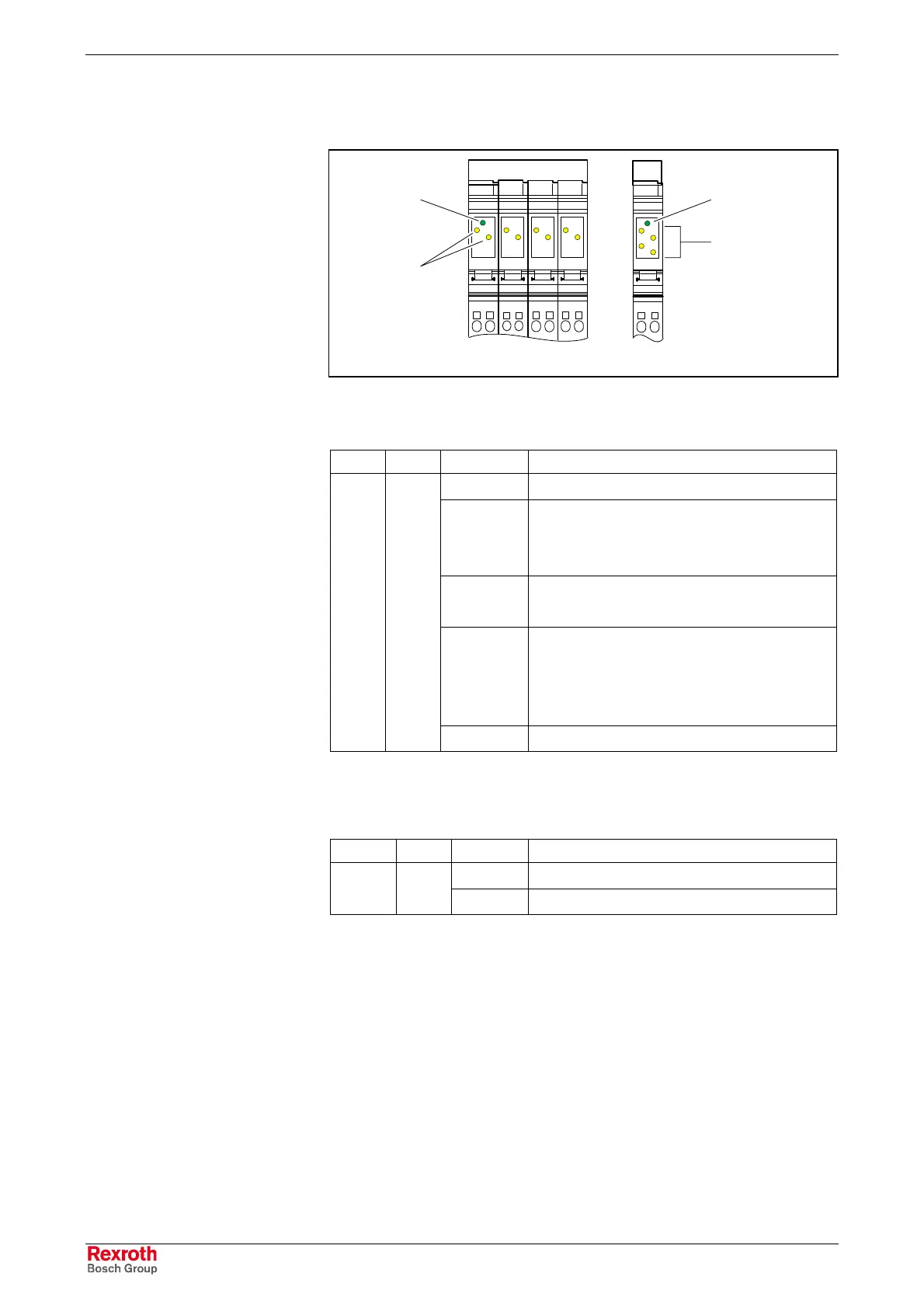
Indicators on the Input/Output Modules
12
11
12
11
12
11
12
11
12
11
1
2
D
1
2
D
1
3
2
4
1
2
1
2
1
2
1
2
Modulanzeige.FH9
Fig. 9-27: Indicators on the input/output modules
The following states are indicated by the input/output modules:
LED Color Status Description of LED states
On Local bus active
Flashing:
0.5 Hz
(slow)
Logic voltage available, local bus not active
2 Hz
(medium)
Logic voltage available, local bus active,
periphery error pending
4 Hz
(fast)
Logic voltage available; module upstream of
the flashing module failed; or module itself is
defective.
Modules downstream of the flashing module
are not included in the configuration scope.
D
(1)
Green
Off Logic voltage not available, local bus not active
Fig. 9-28: Diagnostic LED of input/output modules
The status of the input or output is indicated by the corresponding yellow
LED.
LED Color Status Description of LED states
On The assigned input/output is set.
1, 2, 3, 4
(2)
Yellow
Off The assigned input/output is not set.
Fig. 9-33: Status LEDs of input/output terminals
Assignment of status LED to input/output
Please refer to the functional description for information on the
assignment of a status LED to the corresponding input/output.
Indicators on Other Inline Modules
Please refer to the functional description for information on the diagnostic
and status indicators on other Inline modules (e. g. functional modules or
power modules).
Diagnostics
Status
Buy: www.ValinOnline.com | Phone: 844-385-3099 | Email: CustomerService@valin.com

 Loading...