IndraControl L40 Structure of the Rexroth Inline Terminals 9-1
DOK-CONTRL-IC*L40*****-PR03-EN-P
9 Structure of the Rexroth Inline Terminals
9.1 Basic Structure of Terminals of the Low Signal Level
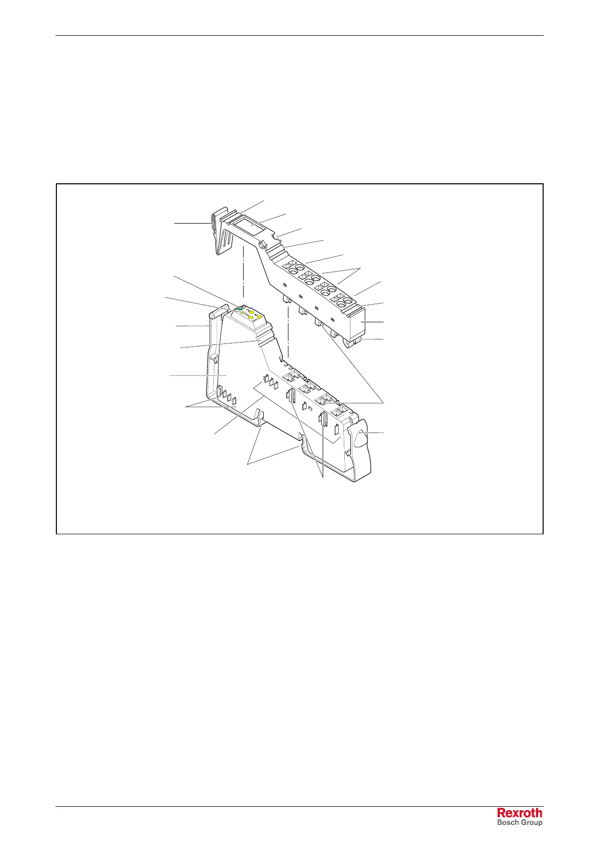
Independently of its function and its overall width, a Rexroth Inline module
of the low signal level consists of the electronic socket (in short: socket)
and the plug-in connector (in short: connector).
Rear connector shaft latch
Rear release mechanism
Diagnostic and status
indicators
Colored function
coding
ZBFM labeling field for
module identification
Electronic socket
Data routing
Voltage routing
Latch on mounting rail
Feather key of the
keyway/feather key
connection
Front release mechanism
Connector
Slot coding
Front connector shaft latch
ZBFM labeling field for signal 3/4
FE or signal terminals 3/4
Potential terminals
Signal terminals 1/2
ZBFM labeling field for signal 1/2
Labeling field slot
Transparent field
ZBFM labeling field for connectors
ModulPrinzip.FH9
Fig. 9-1: Basic structure of a Rexroth Inline modules
The most important components of those shown in Fig. 9-1 are described
in the chapters "Elektronic Socket" on page 9-1 and "Connectors" on
page 9-2.
ZBFM: Zack marker strips, flat (also see the chapter entitled
"Identification of Function and Labeling" on page 9-5).
9.2 Electronic Socket
All electronic parts of the Rexroth Inline module as well as the voltage and
data jumpers are accommodated in the electronic socket.
By default, the electronic sockets for terminals of the low signal level are
available in terminal widths of 8 terminal points (8-slot connector) and 2
terminal points (2-slot connector). Any other dimensions are combinations
of the two above mentioned basic terminal widths (also refer to the
chapter entitled "Housing Dimensions of the Modules of the Low Signal
Level" on page 9-8).
Overall Widths
Buy: www.ValinOnline.com | Phone: 844-385-3099 | Email: CustomerService@valin.com

 Loading...