IndraControl L40 Connections and Interfaces 7-25
DOK-CONTRL-IC*L40*****-PR03-EN-P
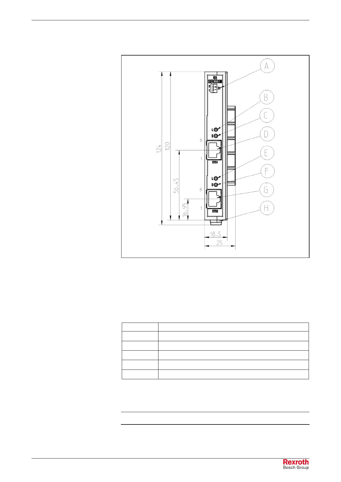
CFL01.1-R3 SERCOS III Function Module
CFL01.1-R3.TIF
A S1, switch for slot number
B Indicator (PORT1) LINK, green
C Indicator (PORT1) ACTIVITY, yellow
D X7S1, PORT1 – SERCOS III interface (RJ45)
E Indicator (PORT2) LINK, green
F Indicator (PORT2) ACTIVITY, yellow
G X7S2, PORT2 – SERCOS III interface (RJ45)
H Mounting rail interlock
Fig. 7-37: SERCOS III module
Pin Meaning
1 TX+ Transmitted data plus
2 TX- Transmitted data minus
3 RX- Received data plus
6 RX- Received data minus
Housing Shield
Fig. 7-38: Pin assignment of the X7S1, X7S2 connector
Bosch Rexroth recommends the use of an STP cable of category 5. You
will find cables for this interface on page 11-7.
Note: Cable fixing during installation required!
For further descriptions please refer to the particular system-
specific manual.
X7S1, X7S2
SERCOS III Interface
Buy: www.ValinOnline.com | Phone: 844-385-3099 | Email: CustomerService@valin.com

 Loading...