IndraControl L40 Structure of the Rexroth Inline Terminals 9-3
DOK-CONTRL-IC*L40*****-PR03-EN-P
3 Extended double-signal connector
This gray connector is used for connecting four signals as 3-
wire connection (e. g. digital input/output signals).
Color Signal at the terminal point
Red +
Blue -
Green / yellow Functional earth ground
Fig. 9-3: Color-coding of the terminal points
12
1
2
3
4
1
2
3
4
A
12
1
2
3
4
1
2
3
4
12
1
2
3
4
1
2
3
4
12
1
2
3
4
1
2
3
4
C D
12
1
2
3
4
1
2
3
4
5
6
5
6
B2B1
Stecker.FH9
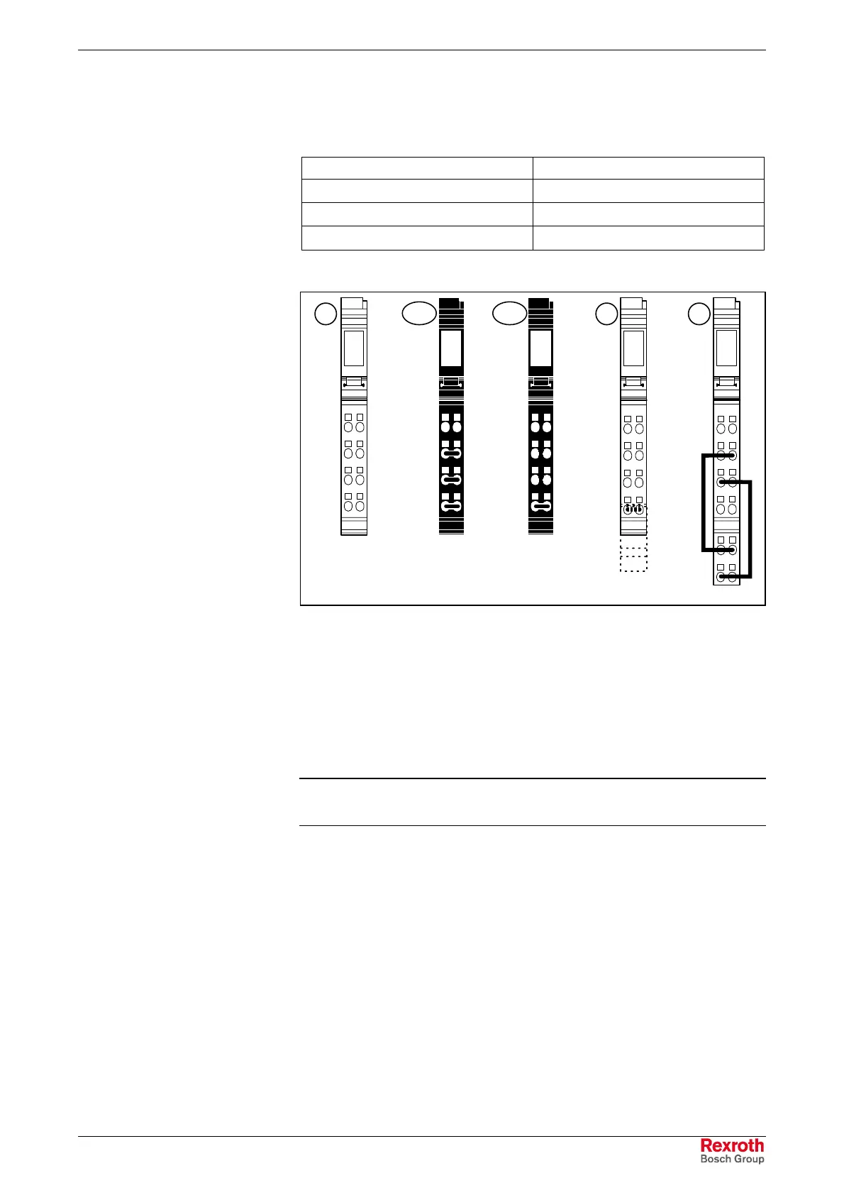
L: A Gray connector for peripheral connection
B1 Black connector for PWR/IN and SEG/F supply SEG/F
(Ordering designation: R-IB IL SCN-PWR IN-CP)
B2 Black connector for supply terminals of the
IndraControl L40
(from connector set R-IB IL CML S01-PLSET)
C Gray shield connector for analog terminals
D Large gray connector for peripheral connection
Fig. 9-4: Connector design
Note: Connector B1 must not be used for supplying the
IndraControl L40.
Connectors with integrated jumpering of terminal points are shown in
Fig. 9-4.
The shield connector is jumpered by the shield connection. All other
connectors are jumpered by a connection of the terminal points.
Interior Design of the
Connectors
Buy: www.ValinOnline.com | Phone: 844-385-3099 | Email: CustomerService@valin.com

 Loading...