IndraControl L40 Structure of the Rexroth Inline Terminals 9-7
DOK-CONTRL-IC*L40*****-PR03-EN-P
In addition to the above labeling of the modules, you can label the slots,
terminal points and connections with zack marker strips (ZBFMs) and
labeling fields.
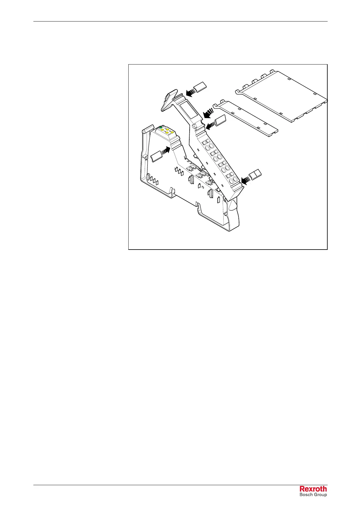
1
2
3
4
5
Modulbeschr.FH9
Fig. 9-9: Labeling of modules
There are various possibilities for labeling slots and terminal points:
1 You can label each connector individually with zack marker strips.
2 / 3 As an option, you can use a large labeling field.
This labeling field is available in two widths, either as labeling field
covering only one connector (2) or as labeling field covering four
connectors (3). Thus, you can label each channel individually with
continuous text. In the upper connector head, there is a
receptacle to attach the labeling field to the connector(s). The
labeling field can be moved up and down. A small catch at both
end positions allows the labeling field to keep its position.
4 / 5 You can label each signal with zack marker strips. With double-
signal connectors, the upper keyway (4) is provided for labeling
the signals 1/2, and the bottom keyway (5) for the signals 3/4.
6 The electronic socket provides the possibility of labeling each slot
individually with zack marker strips. If the connector is latched
onto the socket, this labeling is hidden.
You can clearly assign connector and slot by using the labeling field at the
connector and on the electronic socket.
Additional Labeling
Buy: www.ValinOnline.com | Phone: 844-385-3099 | Email: CustomerService@valin.com

 Loading...