8-6 Installation and Maintenance IndraControl L40
DOK-CONTRL-IC*L40*****-PR03-EN-P
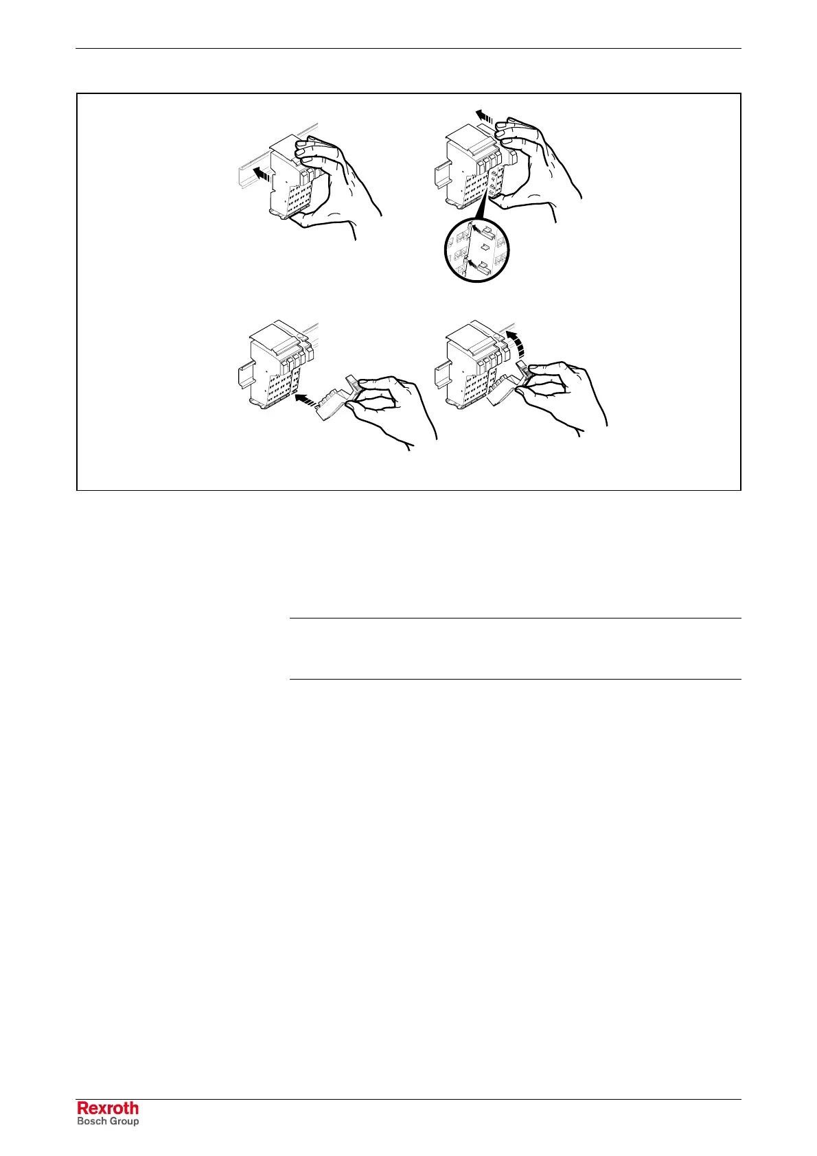
A B
CD
Modulaufrasten.FH9
Fig. 8-4: Latching on a module
Dismounting the Inline Modules
Proceed as follows to remove a module (Fig. 8-5):
• Remove the labeling field, if present (A1 in Fig. A).
Note: If any of the modules is provided with more connectors than
one, all these connectors must be removed from the module.
The sections below describe the removal of a 2-slot module.
Pry out the connector of the module to be removed by pressing on the
rear connector shaft latch (A2 in Fig. A).
• Remove the connector (Fig. B).
• Remove the adjacent connectors of the neighboring modules (Fig. C).
This ensures that the feathers of the voltage jumpers and the
keyway/feather key connection are prevented from damage. Moreover,
the module can be accessed more easily.
• Actuate the release mechanism (D1 in Fig. D) and remove the
electronic socket perpendicularly to the top-hat rail (D2 in Fig. D). If
you have failed to loosen the connector of the neighboring module to
the left, this connector now comes loose to protect the feathers of the
voltage jumper and the keyway/feather key connection.
Buy: www.ValinOnline.com | Phone: 844-385-3099 | Email: CustomerService@valin.com

 Loading...