IndraControl L40 Structure of the Rexroth Inline Terminals 9-5
DOK-CONTRL-IC*L40*****-PR03-EN-P
9.4 Identification of Function and Labeling
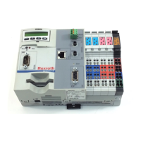
For visual identification of their function, the modules are color-coded (1 in
Fig. 9-6).
1
Funktionskennzeichnung.FH9
Fig. 9-6: Identification of function
The various functions are identified by the following colors:
Color Module function
Light-blue Digital input, 24 V range
Pink Digital output, 24 V range
Blue Digital input, 120/230 V range
Red Digital output, 120/230 V range
Green Analog input
Yellow Analog output
Orange Field bus coupler, function modules *)
Black Power terminal / segment terminal
Fig. 9-7: Color coding of the modules:
Note: All accepted modules are illustrated in chapter "Accessories"
as of page 11-4.
The color coding of the terminal points is described above (on this page).
Connector Identification
Buy: www.ValinOnline.com | Phone: 844-385-3099 | Email: CustomerService@valin.com

 Loading...