7-28 Connections and Interfaces IndraControl L40
DOK-CONTRL-IC*L40*****-PR03-EN-P
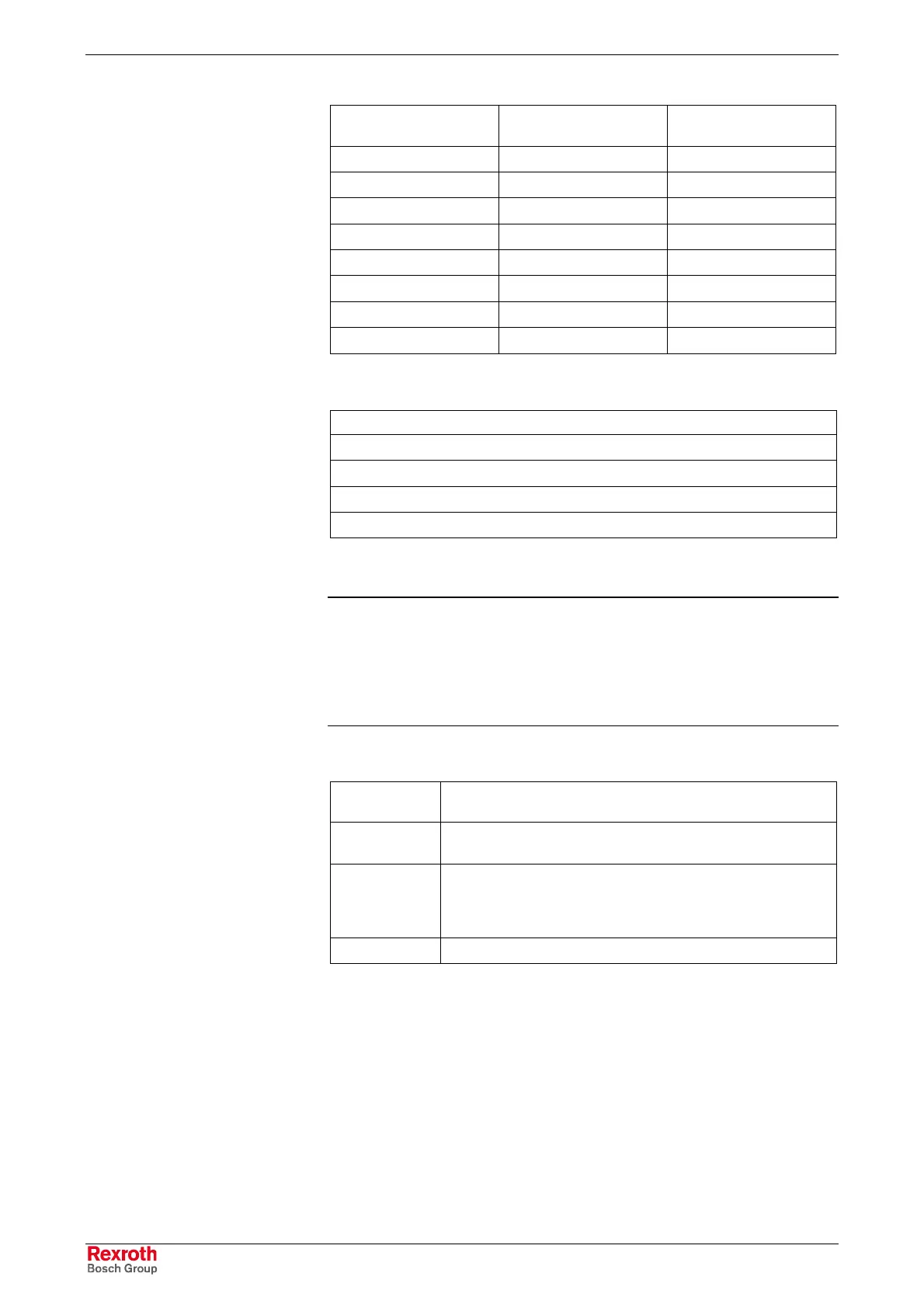
Input connector
X2I1 connection
Input/output connector
X2D1 connection
Output connector
X2O1 connection
Input 0 Input/output 0 Output 0
Input 1 Input/output 1 Output 1
Input 2 Input/output 2 Output 2
Input 3 Input/output 3 Output 3
Input 4 Input/output 4 Output 4
Input 5 Input/output 5 Output 5
Input 6 Input/output 6 Output 6
Input 7 Input/output 7 Output 7
Fig. 7-41: Input and output connectors X2I1, X2D2 and X2O1
Feeder connector X1S connection
24 V (+)
S (sensor supply)
GND (-)
FE
Fig. 7-42: Feeder connector X1S
Note: The function module has to be grounded with two 0.5 mm²
conductors at the FE plug and socket connections. These
conductors must have a length of maximum 0.5 m.
The FE functional earth ground is intended to discharge
disturbances. It is not provided as a protection against electric
shock for persons.
The status LED shows three states:
Light-emitting
diode Stat
Meaning
Green Supply voltage available.
Module ready for operation.
Red Supply voltage is missing.
Short-circuit or overload at one or several outputs.
PCI interface defective (module defective).
Watchdog error (module is not addressed by the system).
Off Supply voltage of the control is missing.
Fig. 7-43: States of the status LED
Interfaces
Indicators
Buy: www.ValinOnline.com | Phone: 844-385-3099 | Email: CustomerService@valin.com

 Loading...