7-36 Connections and Interfaces IndraControl L40
DOK-CONTRL-IC*L40*****-PR03-EN-P
WARNING
Damages of the module!
⇒
If the maximum permissible current consumption of
the function module is exceeded, components of the
module can be destructed
⇒
Removing and inserting the spring terminals under
voltage can damage the electrical contacts
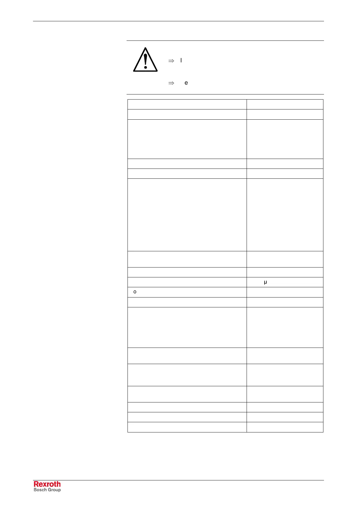
Number of outputs 16
Connection method 1-wire connection
Output type
• Semiconductor outputs,
non-saving
• Protected, with automatic
restart
• Current-carrying
Electrical isolation to the logic supply Yes
Output voltage, nominal value 24 V
Rated output current:
Nominal value
Maximum value according to DIN EN 61131-2
1-signal
0-signal (leakage current)
UL rating:
• General Purpose
• Tungsten
0.5 A
≤ 0.6 A
2 mA ... 0.6 A
≤ 0.5 mA
0.5 A
5 W
Parallel connection of outputs Yes, but only within one half
byte (0-3;4-7 etc.)
Maximum total current of outputs 4 A
Output delay time (ohmic load) < 100
µ
s
Contactor size (at 1 Hz) (inductive load) SG1 (6.2 W)
Lamp load (at 8 Hz) 5 W
Overload protection:
• Typical current level, causing switch-off
• Minimum current level, causing switch-off
• Automatic restart with reduced load
1.2 A
0.6 A
After approx. 10 ms
Overload indicator Red stat. LED for all
16 outputs
Voltage reduced on circuit interruption in the
nominal operating mode, limited to
Electronically limited to
(Vext – 50 V)
Typ. 26 V
Reverse voltage protection Ensured without connected
load
Supply voltage according to EN 61131-2 24 V DC
Open-circuit power consumption from 24 V Typ. 50 mA
Cable length (unshielded) < 100 m
Fig. 7-53: Data of digital outputs
Digital Outputs
Buy: www.ValinOnline.com | Phone: 844-385-3099 | Email: CustomerService@valin.com
 Loading...