9-4 Structure of the Rexroth Inline Terminals IndraControl L40
DOK-CONTRL-IC*L40*****-PR03-EN-P
Note: To avoid malfunctions, only latch the connector onto the
terminal it is intended for. Refer to the specific data sheet of
each module to select the appropriate connector. The black
connector may not be latched onto a module that is intended
for a double-signal connector. Any reversal would lead to a
short-circuit between the two signal terminal points (1.4 - 2.4).
Important: Place only a black B2-type connector (from connector
set R-IB IL CML S01-PLSET) on the supply terminal at
the IndraControl L40! The terminal point jumpering
ensures that the potential is transmitted via the
jumpering in the connector and not via the module
board.
It is possible to prevent the mismatching of connectors by coding socket
and connector.
1
1
1
2
1
A
1
C
1
B
Steckerkodierung.FH9
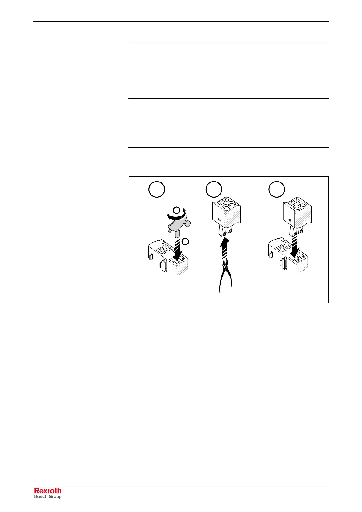
Fig. 9-5: Connector coding
• For this purpose, put a coding profile into the coding keyway in the
socket (1) and pull it off the small plate (2) by rotation (Fig. 9-5/A).
• Use a side-cutting pliers to cut the respective coding tab off the
connector (Fig. 9-5/B).
Now, only socket and connector of the same coding fit together
(Fig. 9-5/C).
Connector Coding
Buy: www.ValinOnline.com | Phone: 844-385-3099 | Email: CustomerService@valin.com

 Loading...