IndraControl L40 Connections and Interfaces 7-33
DOK-CONTRL-IC*L40*****-PR03-EN-P
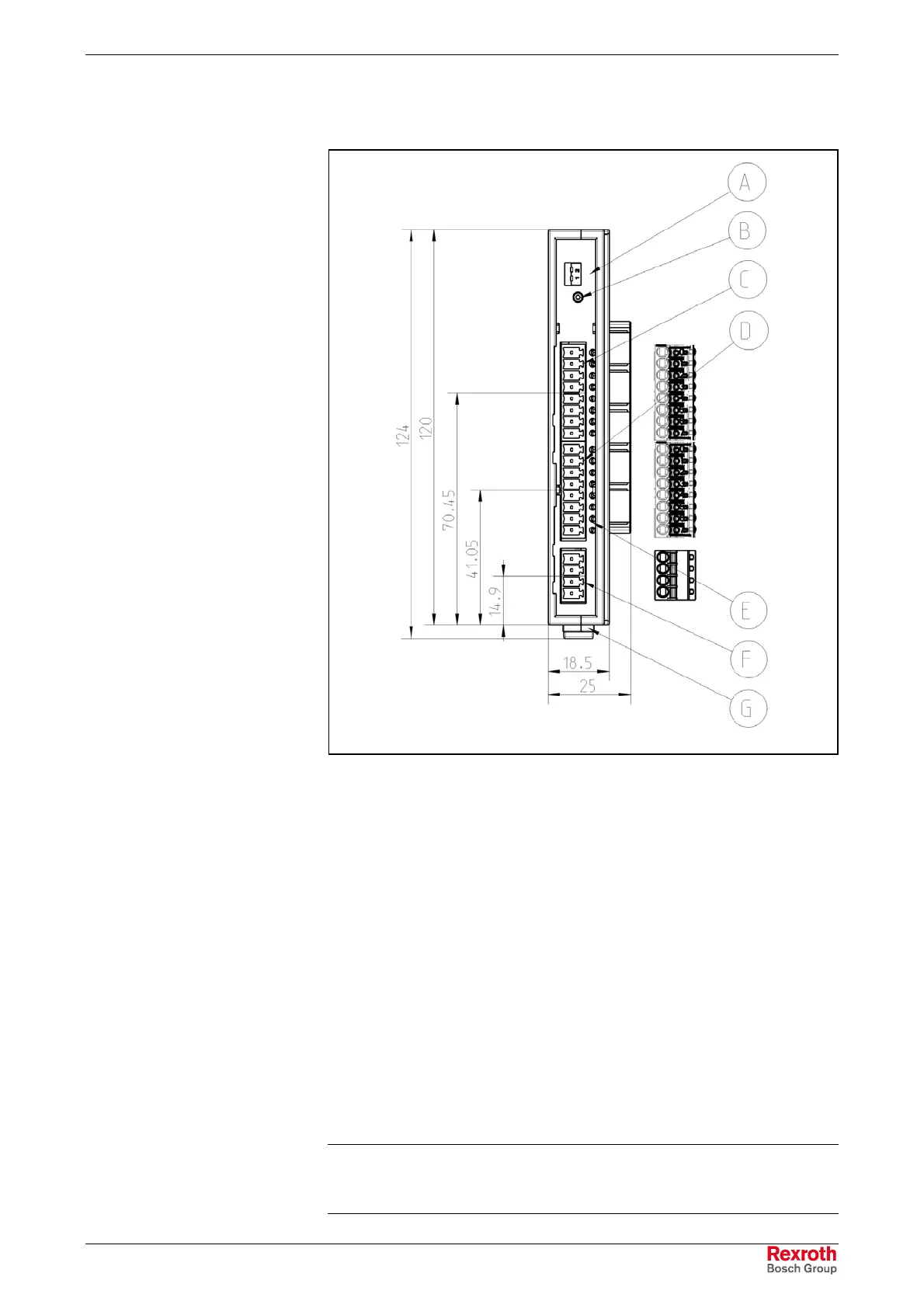
CFL01.1-N1 Cam Switch Function Module
CFL01.1-Y1.tif
A S1, switch for slot number
B Stat, status display
C X2O1, digital outputs
D X2O1, digital outputs
E Status LED of the outputs
F X1S, load supply of the outputs
G Mounting rail interlock
Fig. 7-48: Cam switch function module
Each cam switch function module (also named as Programmable Limit-
Switch, function module PLS) is equipped as follows:
• 16 outputs
• 2 MINI COMBICON plug and socket connections each with 8 outputs
(X2O1 and X2O2)
• 1 MINI COMBICON plug and socket connection with power supply and
functional earth ground
• LED status indicator for each output
• LED status indicator power fail and overload
• current per output is 250 mA when nominal voltage is 24 V (see note)
Note: The maximum current consumption per output is limited to
500 mA. However, the total of all output currents must not
exceed 4 A.
Properties
Buy: www.ValinOnline.com | Phone: 844-385-3099 | Email: CustomerService@valin.com

 Loading...