IndraControl L40 Structure of the Rexroth Inline Terminals 9-11
DOK-CONTRL-IC*L40*****-PR03-EN-P
9.6 Electrical Voltage and Data Routing
An essential feature of the Rexroth Inline product family is the internal
voltage routing system. The electrical connection between the individual
station devices is established automatically when the station is set up.
When the individual station devices are latched to each other, a conductor
rail is set up for the respective electric circuit. Mechanically, this contact is
realized by the blade and spring contacts of the neighboring modules
latching into each other.
Using a special segment circuit, the user does not have to establish the
additional external potential transmission to the neighboring modules.
In one station, two independent electric circuits have been realized:
• Logic circuit
• Circuit of peripheral equipment
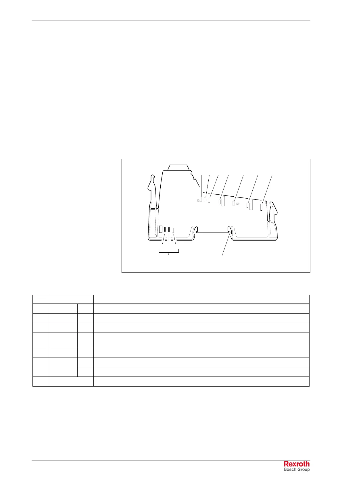
12
3
4567
8
abc
(9)
Rangierung.FH9
Fig. 9-14: Voltage and data routing
No. Function Meaning
1 7.5 V U
L
Supply of module electronics (logic supply)
2 24 V U
ANA
Peripheral supply voltage for analog modules
3 GND Ground of the logic supply voltage and the peripheral supply voltage for analog modules
4 24 V U
S
Supply of the segment circuit (if necessary protected against overload)
This voltage jumper does not exist at the 120 V and 230 V voltage levels.
5 24 V U
M
Supply of the main circuit (if necessary protected against overload)
6 GND GND Ground of the segment and main voltage supply (neutral conductor)
7 FE FE Functional earth ground
(9) (FE spring) FE contact to the top-hat rail (not in all modules)
Fig. 9-15: Voltage jumpers (see Fig. 9-14)
Buy: www.ValinOnline.com | Phone: 844-385-3099 | Email: CustomerService@valin.com
 Loading...