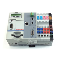
9-6 Structure of the Rexroth Inline Terminals IndraControl L40
DOK-CONTRL-IC*L40*****-PR03-EN-P
Numbering of the terminal points is illustrated by means of an 8-slot
module.
12
1
2
3
4
1
2
3
4
12
1
2
3
4
1
2
3
4
12
1
2
3
4
1
2
4
12
1
2
3
4
1
2
3
4
3
1234
1
2
3
4
1
2
3
1
2
3
4
1
1.1
1.2
1.3
2.1
2.2
2.3
2.4
2
1.4
4
X.Y
Klemmpunktnumm.FH9
Fig. 9-8: Numbering of terminal points
The slots (connectors) on a socket are numbered consecutively (1 in
Fig. 9-8). These numbers are not specified on the module.
On each connector, the terminal points are identified by X.Y.
X is the number of the terminal point row on the connector and is
indicated on the top of the respective terminal point row (2 in Fig. 9-8).
Y is the number of the terminal point in a row and is indicated directly at
the terminal point (3 in Fig. 9-8).
Thus, the position of the slot and terminal point can be exactly
determined. For instance, the gray connection (4 in Fig. 9-8) is numbered
as follows: slot 3, terminal point 2.3.
Labeling/Numbering of Terminal
Points
Slot/Connector
Terminal Point
Buy: www.ValinOnline.com | Phone: 844-385-3099 | Email: CustomerService@valin.com

 Loading...