7-30 Connections and Interfaces IndraControl L40
DOK-CONTRL-IC*L40*****-PR03-EN-P
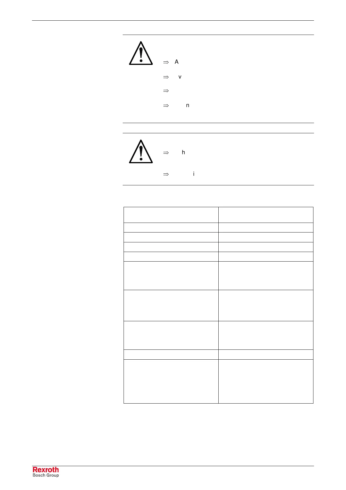
WARNING
Destruction of the module by improper
connection!
⇒
Avoid polarity reversal with simultaneous short-circuit
of the output lines
⇒
Avoid polarity reversal with simultaneous connection
of externally polarized suppressor diodes
⇒
Do not apply an external voltage greater than the
supply voltage
⇒
Do not connect sensors to an external voltage.
Sensors have to be supplied from the sensor supply
(X1S).
WARNING
Damages of the module!
⇒
If the maximum permissible current consumption of
the function module is exceeded, components of the
module can be destructed
⇒
Removing and inserting the spring terminals under
electrical voltage can damage the electrical contacts
Number of inputs 16 (8 of the 16 can be selected bit by
bit as input or output)
Connection method 1-wire connection
Input type Type 1, according to EN 61131-2
Electrical isolation to the logic supply Yes
Reverse voltage protection Yes
Input voltage:
Nominal value at "0"
Nominal value at "1"
-3 V … +5 V
11 V … 30 V
Input current:
Nominal value at "0"
Nominal value at "1"
< 2.5 mA
2.8 mA … 6 mA
Delay time:
If "0" to "1"
If "0" to "1"
Typ. 40 µs, max. 50 µs
Typ. 45 µs, max. 55 µs
Cable length (unshielded) < 100 m
Sensor supply (connection "S")
Output voltage, nominal value
Nominal current (total)
Short-circuit protection,
overcurrent protection
24 V
0.2 A
Typ. 1.2 A
Fig. 7-45: Data of digital inputs
Digital Inputs X2I1, X2D1
Buy: www.ValinOnline.com | Phone: 844-385-3099 | Email: CustomerService@valin.com
 Loading...