Options
7-23
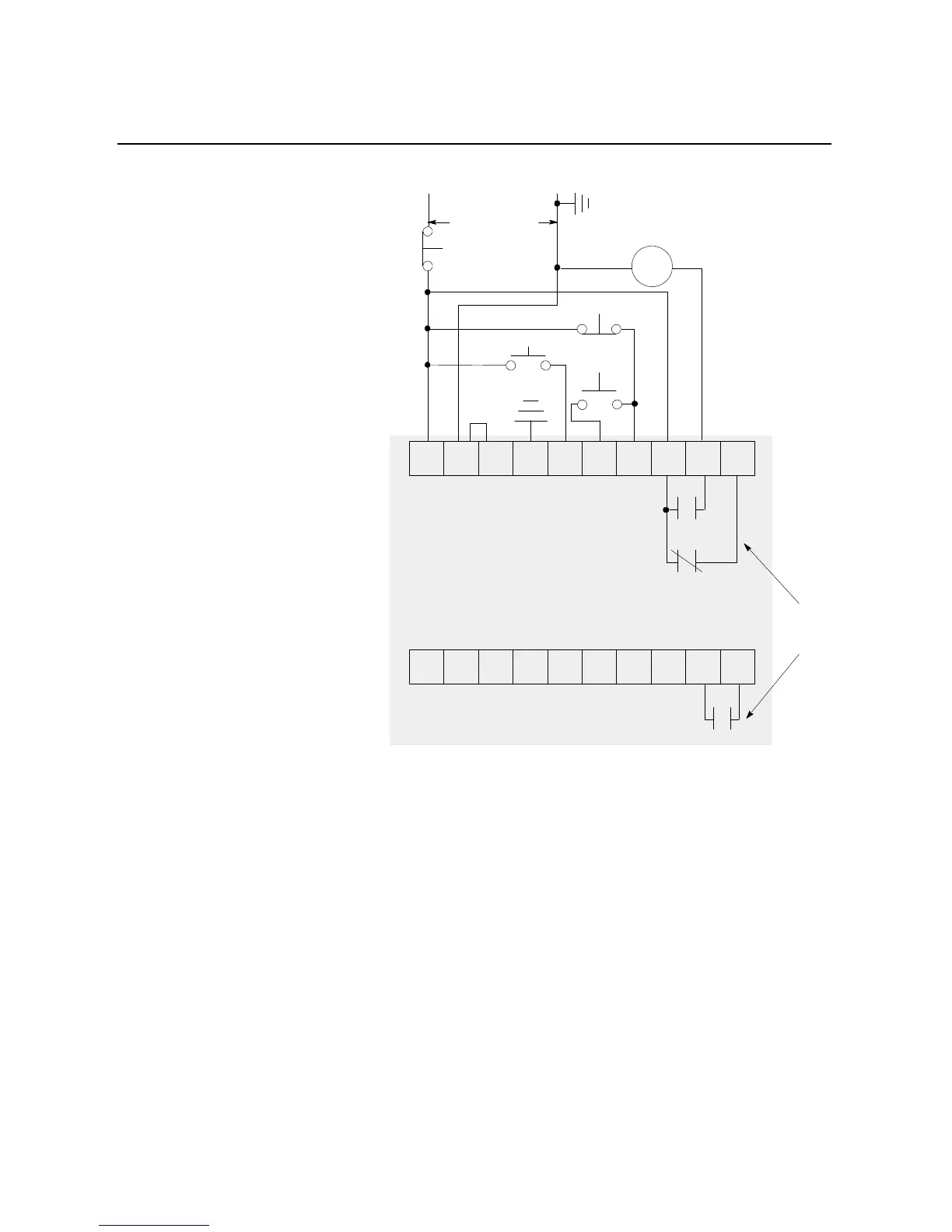
Figure 7.19 Typical Wiring Diagram for the Slow Speed with Braking Option
with an Isolation Contactor
①
Customer supplied.
②
Refer to the controller nameplate to verify the rating of the control power input voltage.
Note: Refer to Chapter 3 for typical power circuits.
Brake
➀
Stop
➀
IC
➀
Control Power
➁
Slow Speed
➀
Start
➀
11 12 13 14 15 16 17 18 19 20
21 22 23 24 25 26 27 28 29 30
Internal
Auxiliary
Contacts
Auxiliary contacts set
for Normal
SMC Dialog Plus
Control Terminals

 Loading...


