47 / 280
2.4. Connector features
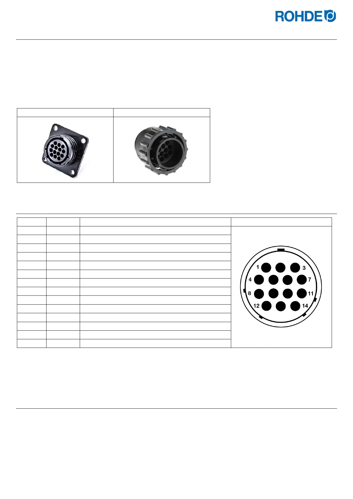
The control unit is connected to the kiln via a 14-pin connector.
Features:
• CPC 14 connector
• 14-pin screw connection
• Bayonet fitting
The black 14-pin socket provided for this is located on the switch cabinet of the kiln (near the electrical supply line).
2.5. Plug pin assignment
1 X Thermocouple 1 +
2 X Thermocouple 1 -
3 − Not used
4 − Not used
5 − Not used
6 − Not used
7 X Additional switch output (230 V)
8 X L1 feed 230 V AC
9 X N feed
10 − Not used
11 − Not used
12 X Safety contactor switch output
13 X Neutral conductor switch output
14 X Zone 1 switch output
Note:
The wiring of the mating CPC 14 socket can vary between kiln manufacturers!
2.6. Kiln contactor protection circuit
The coil of each kiln contactor should be suppressed with an RC circuit. RC circuits must be connected directly across the
coil terminals on each contactor. ROHDE kilns are delivered this way as standard. For kilns from other manufacturers,
suitable products are available as accessories from contactor manufacturers.
 Loading...