5 | Assembly and installation
Page 22 of 104 CIRUS
®
UPT-6400 VERSION 1 | EN-US
5.5.1 Power supply
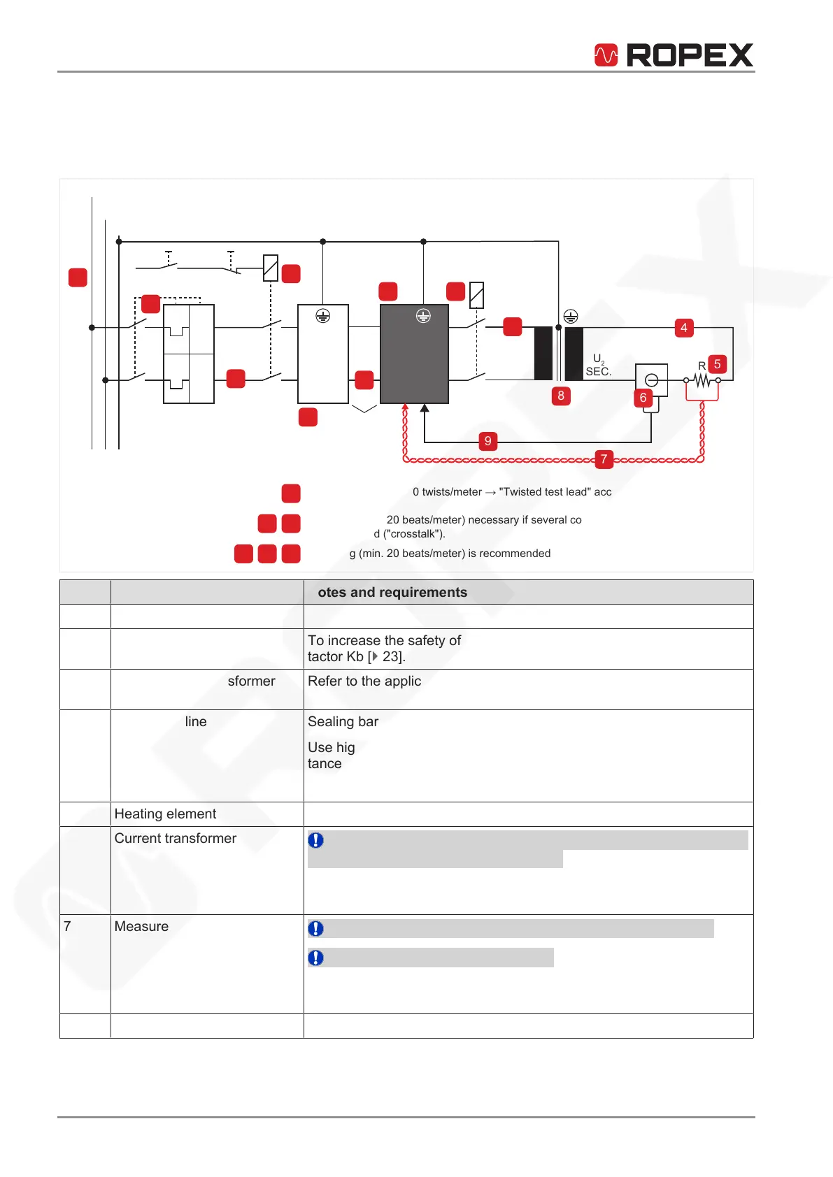
The following illustration shows a standard application.
When making electrical connections, also refer to the section Connection diagram as
well as to the application report.
Always twist (min. 20 twists/meter → "Twisted test lead" accessory)
Twisting (min. 20 beats/meter) necessary if several control circuits are used
together
are relocated ("crosstalk").
Twisting (min. 20 beats/meter) is recommended to improve the EMC behavior.
L1(L1)
N(L2)
ON
Kc
I>
I>
Short
cables
U
R
U
1
PRIM.
U
2
SEC.
I
R
R
Ka
Kb
(EMER-
GENCY)
OFF
PE
5
11
1
13
4
6
9
14
7
8
15
2
3
10
12
7
4 9
3 10 12
Pos. Component Notes and requirements
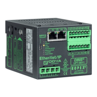
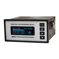
1 Temperature controller
2 Contactor Kb To increase the safety of machine operation, refer to the section Con-
tactor Kb [}23].
3 Primary pulse transformer
lines
Refer to the application report.
4 Secondary line Sealing bar connection to the pulse transformer.
Use high-quality connecting elements that ensure low contact resis-
tance with long-term stability.
Refer to the application report.
5 Heating element Refer to section Heat-sealing band and to the application report.
6 Current transformer
NOTICE!Observe the number of ducts for passing the secondary
cable through the current transformer.
Refer to section Current transformer [}17] and to the application re-
port.
7 Measurement cable U
R
NOTICE!Use twisted measuring cables provided by ROPEX.
NOTICE!Input voltage max. 120V.
Refer to section Measurement cable [}18] and to the application re-
port.
8 Pulse transformer
Refer to section Pulse transformer [}16] and to the application report.
 Loading...