Monitoring and error detection | 10
VERSION 1 | EN-US CIRUS
®
UPT-6400 Page 83 of 104
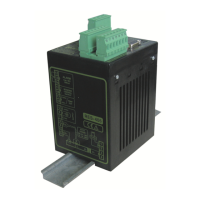
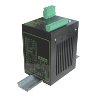
10 Monitoring and error detection
10.1 System monitoring and alarm output
To increase operational safety and prevent faulty heat-sealing, the temperature con-
troller monitors both external wiring as well the internal system.
Error messages and diagnoses are detected by means of hardware and software ap-
plications. This allows the source of faulty operation of the temperature controller to be
localized.
A system fault is reported or differentiated by means of the following indications.
Who reports? How is the fault
reported?
Meaning
Error message on
screen
The alarm, the er-
ror code and the
way in which the
error message is
reset are shown
on the screen.
Indicates that there are faults. The fault con-
tains an error code; refer to section .
Alarm relay
(relay contact ter-
minals 12, 13, 14)
default
3)
NOT ACTIVE
• Execute AUTOCAL functions (error codes
104…106, 211, 302, 303).
Note: If a START signal is sent during this
state, the alarm relay becomes active.
• The system configuration is incorrect and
zero calibration (AUTOCAL function) was
unsuccessful (error codes 111…114); re-
fer to section .
Note: If a START signal is sent during this
state, the alarm relay becomes active.
ACTIVE Indicates that there are faults that prevent
startup (error codes 101…103, 107, 108,
201…203, 304, 307, 308, 9xx).
Tip There are usually external wiring faults.
Error code indicated
via the actual value
output 0…10VDC
(terminals 17+18)
Since there is no need to show the temperature when a fault occurs, the actual value
output is used to display the error in the event of an alarm.
For this purpose there are 13voltage levels offered within the range 0…10VDC, each
of which is assigned an error code.
For statuses that require AUTOCAL, or if the device configuration is incorrect (error
codes 104…106, 111…113, 211), the signal at the actual value output alternates at a
rate of 1 Hz between the voltage value corresponding to the error and the end of the
scale (10VDC, i.e. 300°C or 500°C). If the START signal is present in one of these
states, the voltage value does not change any more.
This means that, via the analog output of a PLC and a respective evaluation, selective
error detection and error display are simple and inexpensive.
Measures to reset the
alarm message
An error message can be reset by pressing Reset or by switching the temperature
controller off and then back on again.
Invalid alarm
messages
Because its operating status is not defined, invalid alarm messages may occur when
the temperature controller is switched off. To prevent false alarms, this has to be taken
into consideration for the evaluation in the higher-ranking controller (e.g.PLC).
3
If the alarm relay has a different configuration than the default, states are reversed.