8 | Functions and settings
Page 58 of 104 CIRUS
®
UPT-6400 VERSION 1 | EN-US
39
33
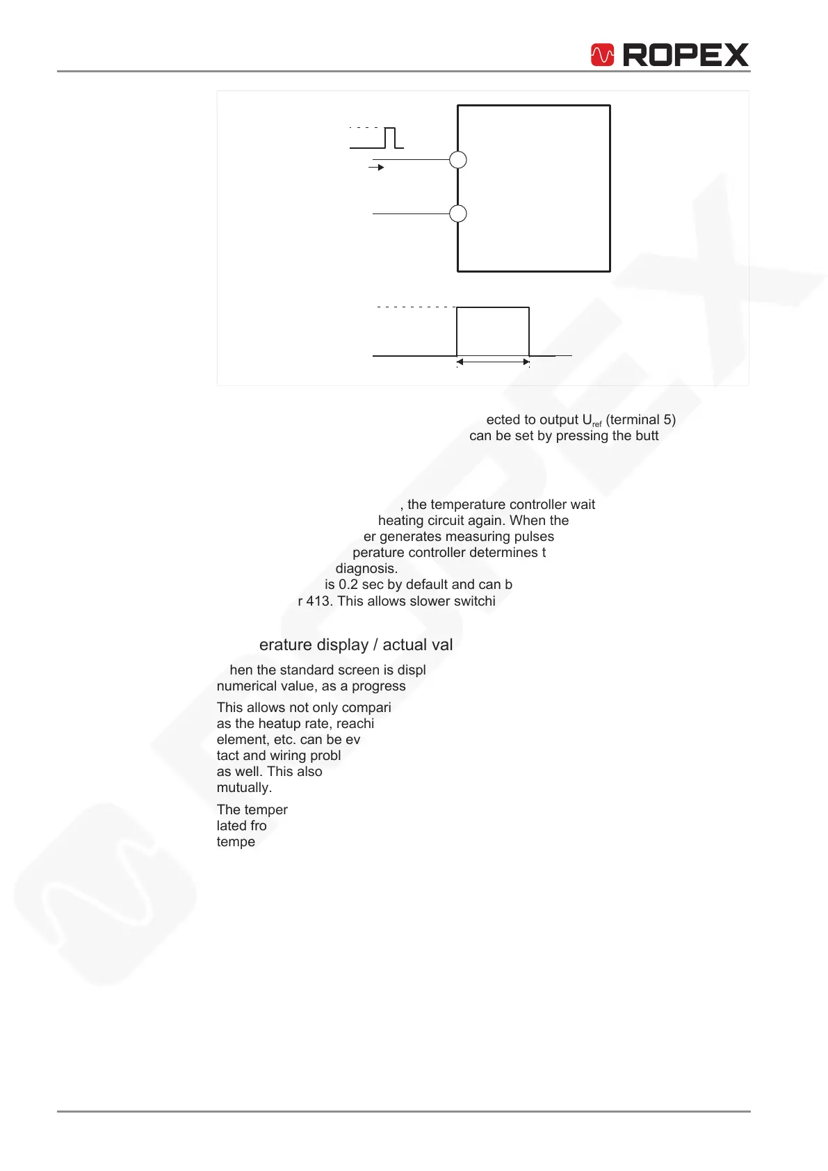
max. 6 mA
+
-
GND
HIGH:
≥ 8 VDC
LOW: ≤ 2 VDC
> 0.1 s
RESET
8-30 VDC
RESET
Temperature controller
Illustration15: Reset signal
Tip
The RESET input (terminal33) can be connected to output U
ref
(terminal5) via an ex-
ternal button. The temperature controller can be set by pressing the button.
8.3.2 Restart delay after reset
After acknowledging an alarm, the temperature controller waits until any contactor
connected has closed the heating circuit again. When the waiting time has elapsed,
the temperature controller generates measuring pulses again. With the aid of the mea-
suring pulses, the temperature controller determines the current actual temperature
and performs error diagnosis.
The restart delay is 0.2sec by default and can be adjusted in the Machine menu,
menu number 413. This allows slower switching contactors to be used.
8.3.3 Temperature display / actual value output
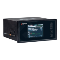
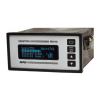
When the standard screen is displayed, the actual temperature is shown as a digital
numerical value, as a progress bar and as a graph.
This allows not only comparisons of the setpoint and actual value. Other criteria such
as the heatup rate, reaching the setpoint in the specified time, cooling of the heating
element, etc. can be evaluated. Faults in the control loop (e.g. loose connections, con-
tact and wiring problems), such as power disruptions, can be detected and interpreted
as well. This also applies when multiple adjacent control loops influence one another
mutually.
The temperature controller supplies an analog signal 0…1VDC that is electrically iso-
lated from the heating circuit to terminals17+18 and that is proportional to the actual
temperature.






 To Next Page