10 | Monitoring and error detection
Page 84 of 104 CIRUS
®
UPT-6400 VERSION 1 | EN-US
10.2 Error messages
Tip
To facilitate error diagnosis, the temperature controller emits 13voltage levels via the
analog output. In the temperature controller, the error messages are more precisely
differentiated and encoded as error codes.
The three-digit error codes can be displayed as follows:
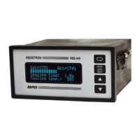
• Temperature controller screen
• For information on the visualization software, refer to the manual for the visualiza-
tion software ROPEXvisual
®
.
Notes
In order to avoid incorrect evaluations, the evaluation of the analog output for the de-
tection of an error message – e.g. in the higher-level control unit – must be carried out
with an adapted tolerance window.
Comply with the analog output tolerances; refer to Technical data.
The following three tables show the assignment of the three-digit error codes to the
voltage level at the analog output. They also contain the causes and the measures re-
quired to remedy the error.
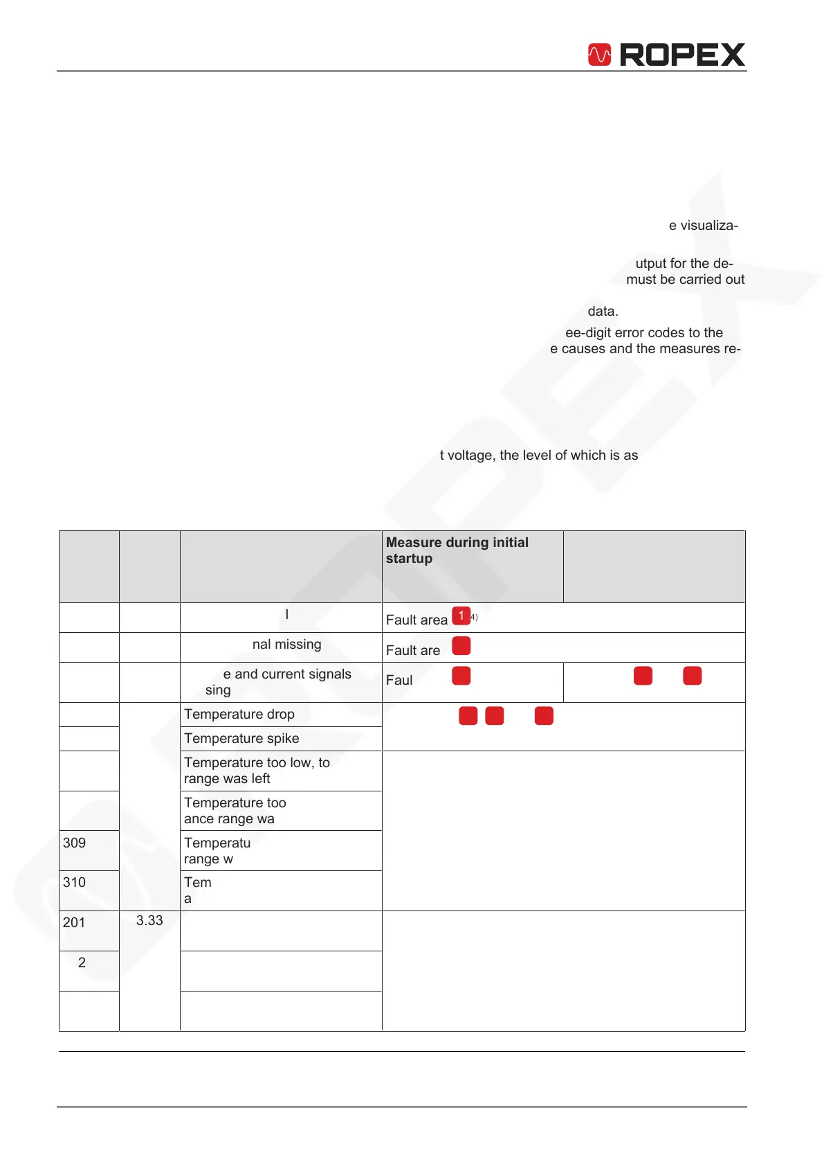
10.2.1 Part 1 of 3: Troubleshooting
The errors are reported as faults.
• The analog output emits constant voltage, the level of which is associated with a
set of error codes.
• Screen content
• Alarm relay is active.
Error
code
Analog
signal
voltage
[V]
Cause Measure during initial
startup
Action if machine is al-
ready in operation, heat-
ing element not changed
101
0.66
No current signal
Fault area
4)
102
1.33
Voltage signal missing
Fault area
4)
103
2.00
Voltage and current signals
missing
Fault area
4)
Fault area
and
107
2.66
Temperature drop
Fault areas
,
and
(loose wire)
4)
108 Temperature spike
307 Temperature too low, tolerance
range was left
Check dimensioning of the pulse transformer.
Check heat extraction through the sealing process.
Verify application through sealing tests.
308 Temperature too high, toler-
ance range was left
309 Temperature too low, tolerance
range was not reached
310 Temperature too high, toler-
ance range was not reached
201
3.33
Line frequency missing/fluctu-
ates
Check mains power supply:
• Line frequency
• Harmonics
• Voltage fluctuations
202 Line frequency too high / fluctu-
ates
203 Line frequency too low / fluctu-
ates
4
Refer to the wiring diagram Fault areas and causes [}87] for further information.






 To Next Page