Monitoring and error detection | 10
VERSION 1 | EN-US CIRUS
®
UPT-6400 Page 87 of 104
Error
code
Analog
signal
voltage
[V]
7)
Cause Measure during initial
startup
Action if machine is al-
ready in operation, heat-
ing element not changed
111
6.66/10
Current signal incorrect, cali-
bration not possible
Fault area
8)
Check configuration
Fault areas
,
and
(loose wire)
8)
112
7.33/10
Voltage signal incorrect, cali-
bration not possible
Fault area
8)
Check configuration
113
8.00/10
Voltage/current signal incorrect,
calibration not possible
Fault areas
and
8)
Check configuration
114
8.66/10
Temperature fluctuates, calibra-
tion not possible
Perform AUTOCAL
And/or fault areas
,
and
(loose contact)
8)
115 External calibration tempera-
ture too high, calibration not
possible
Perform AUTOCAL with external calibration tempera-
ture ≤ 40°C.
116 External calibration tempera-
ture fluctuates, calibration not
possible
Perform AUTOCAL with stable external calibration
temperature.
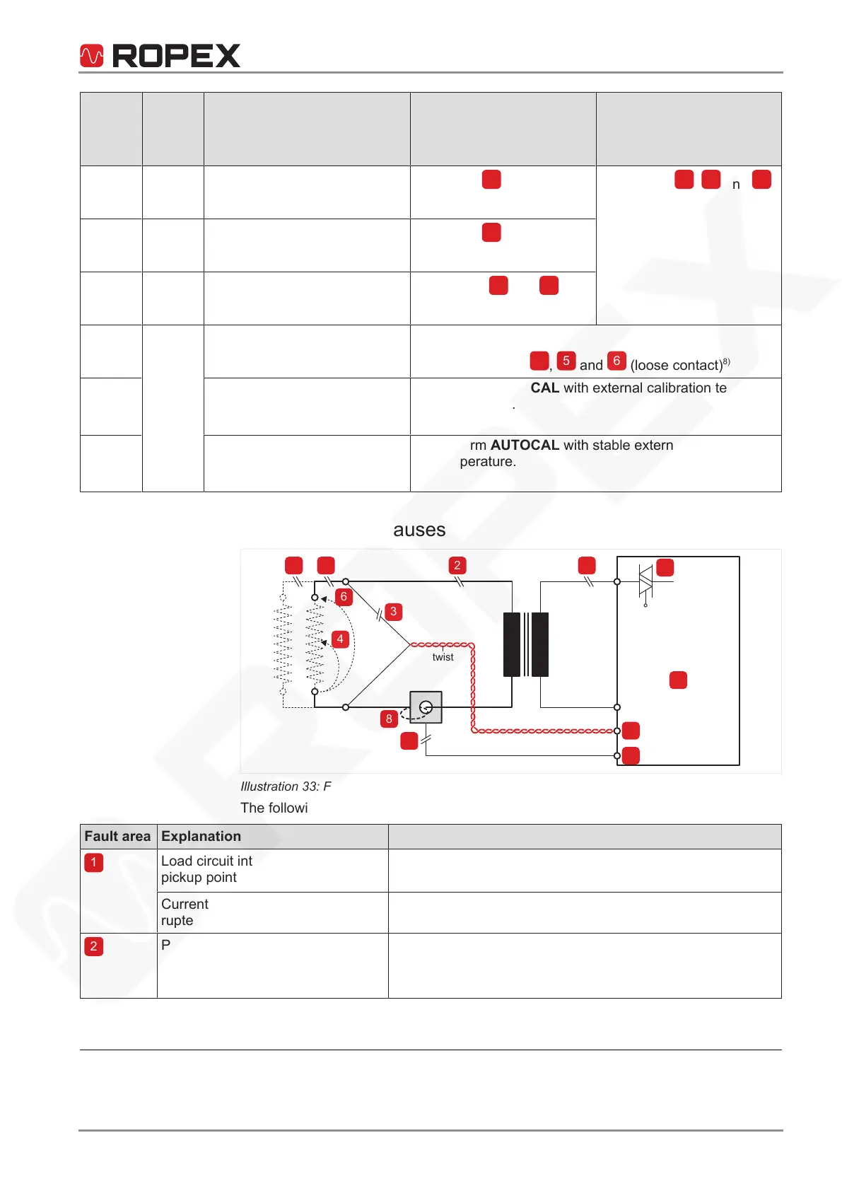
10.3 Fault areas and causes
UR
IR
Temperature
controller
HARDWARE
twist
7
3
1
9
6
5
4
2
8
8
2
9
1
Illustration33: Fault areas and causes
The following table explains the possible causes.
Fault area Explanation Possible causes
Load circuit interrupted after U
R
pickup point
• Wire break, heating element break.
• Contact to heating element is defective.
Current transformer signal inter-
rupted
• I
R
measurement cable from current transformer inter-
rupted.
Primary circuit interrupted
• Wire break, triac in controller defective.
• Primary winding of pulse transformer interrupted.
• Kb contactor open.
7
The voltage at the analog output alternates between the two values.
8
Refer to the wiring diagram Fault areas and causes [}87] for further information.
 Loading...