Technical data | 13
VERSION 1 | EN-US CIRUS
®
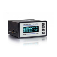
UPT-6400 Page 91 of 104
13 Technical data
13.1 Technical data
NOTICE
Risk of defects and loss of warranty when operation of the device does not
comply with technical specifications
Operating the device in noncompliance with the technical specifications can cause de-
fects and result in loss of warranty.
Comply with the technical specifications.
Element Technical data
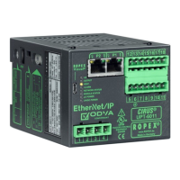
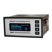
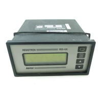
Type of construction Housing to mount control panel
Dimensions Width×height: 144 × 72 mm (front frame)
Width×height: 136 × 66 mm (housing)
Depth (beginning at front of control panel): 161mm (including terminals)
Line voltage
• Connected between neutral conductor and an outer conductor:
• 110VAC -15%…300VAC +10%
or
• Connected between two outer conductors:
• 110VAC -15%…480VAC +10%
Note: The voltage between the line conductor and ground shall not be more than 300
VAC.
Power supply system
• Balanced TN or TT system
• Installation category III
Note: Operation in an IT system is permitted only in agreement with ROPEX. Consult
ROPEX, e-mail info@ropex.de.
Line frequency 50/60Hz
(automatic frequency adjustment)
Heating element type
and temperature range
(Set in the Heating
element menu)
• Temperature range: 200°C, 300°C, 400°C or 500°C
• Temperature coefficient 400…4000ppm/K (variable setting range)
• Temperature coefficient 1700ppm/K (ROPEX CIRUS
®
system)
Analog input (setpoint)
Terminals36+39
0…10VDC, electrically isolated from heating circuit
Equivalent to 0…300°C or 0…500°C
• Input resistance: 40 kΩ, protected from polarity reversal
The setpoint can also be configured in the Settings menu of the temperature con-
troller.
Analog output (actual
value)
Terminals17+18
0…10VDC, I
max
= 5mA, electrically isolated from heating circuit
Equivalent to 0…300°C or 0…500°C
Accuracy: ±1% plus 50mV
Digital logic level
Terminals6, 18, 33, 34,
35, 39
LOW (0V): 0…2VDC
HIGH (24VDC): 8…30VDC (power consumption max.6mA)
Electrically isolated from heating circuit, protected from polarity reversal