Assembly and installation | 5
VERSION 1 | EN-US CIRUS
®
UPT-6400 Page 23 of 104
Pos. Component Notes and requirements
9 Measurement cable, current
I
R
NOTICE!Use twisted measuring cables provided by ROPEX.
Refer to section Measurement cable [}18] and to the application re-
port.
10 Filtered lines
(lines between line filter and
temperature controller)
Refer to the application report.
11 Line filter Do not install unfiltered and filtered lines in the same wiring ducts.
Refer to section Line filters [}17] and to the application report.
12 Unfiltered lines
(lines between voltage supply
and line filter)
Refer to the application report.
13 Overcurrent protective device
Kc
Example: 2-pin circuit breaker or fuse; refer to the application report.
NOTICE!Protects only from short-circuit. Does not protect the
temperature controller.
14 Grid To improve the immunity to interference, the system can be connected
to the same phase when the output is low. Observe the requirements
specified by the electric company in regard to a symmetrical grid load.
15 Contactor Kb For EMERGENCY OFF or EMERGENCY STOP (all-pole)
5.5.1.1 Contactor Kb
A contactor Kb can be installed in the control loop to increase the safety of the ma-
chine.
The contactor Kb causes load break (all-pole), e.g. in conjunction with the alarm out-
put of the temperature controller
A contactor Kb can also be installed in the control loop, e.g. when the system has to
be switched off by the machine controller (PLC) or when a door contact is required.
The load on the contactor Kb is a factor of the specific application; refer to the applica-
tion report.
Tips
Trigger the contactor Kb via the temperature controller alarm relay.
To do this, set the alarm output to inverse (menu number405) and connect the
24VDC supply voltage for the contactor to theNO andCcontacts of the alarm re-
lay.
To prevent errors, first switch on the 24VDC supply voltage before switching on the
supply voltage to the temperature controller.
Use relayK1 or relay K2 to use a contactor supplied with 230V. To do this, configure
relayK1 or relayK2 to Active for alarm (menu number 407 or 408)
5.5.2 Connection diagram
Additional protective equipment as well as the controller for the equipment should be
provided on site.
When making electrical connections, also refer to the section Power supply [}22] as
well as to the application report.
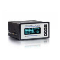
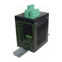
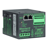
The following illustrations show examples of standard applications.






 To Next Page