EasyManua.ls Logo

Ropex CIRUS UPT-6400 - Page 24

Ropex CIRUS UPT-6400
104 pages
Print Icon
To Next Page IconTo Next Page
To Previous Page IconTo Previous Page
Loading...
5 | Assembly and installation
Page 24 of 104 CIRUS
®
UPT-6400 VERSION 1 | EN-US
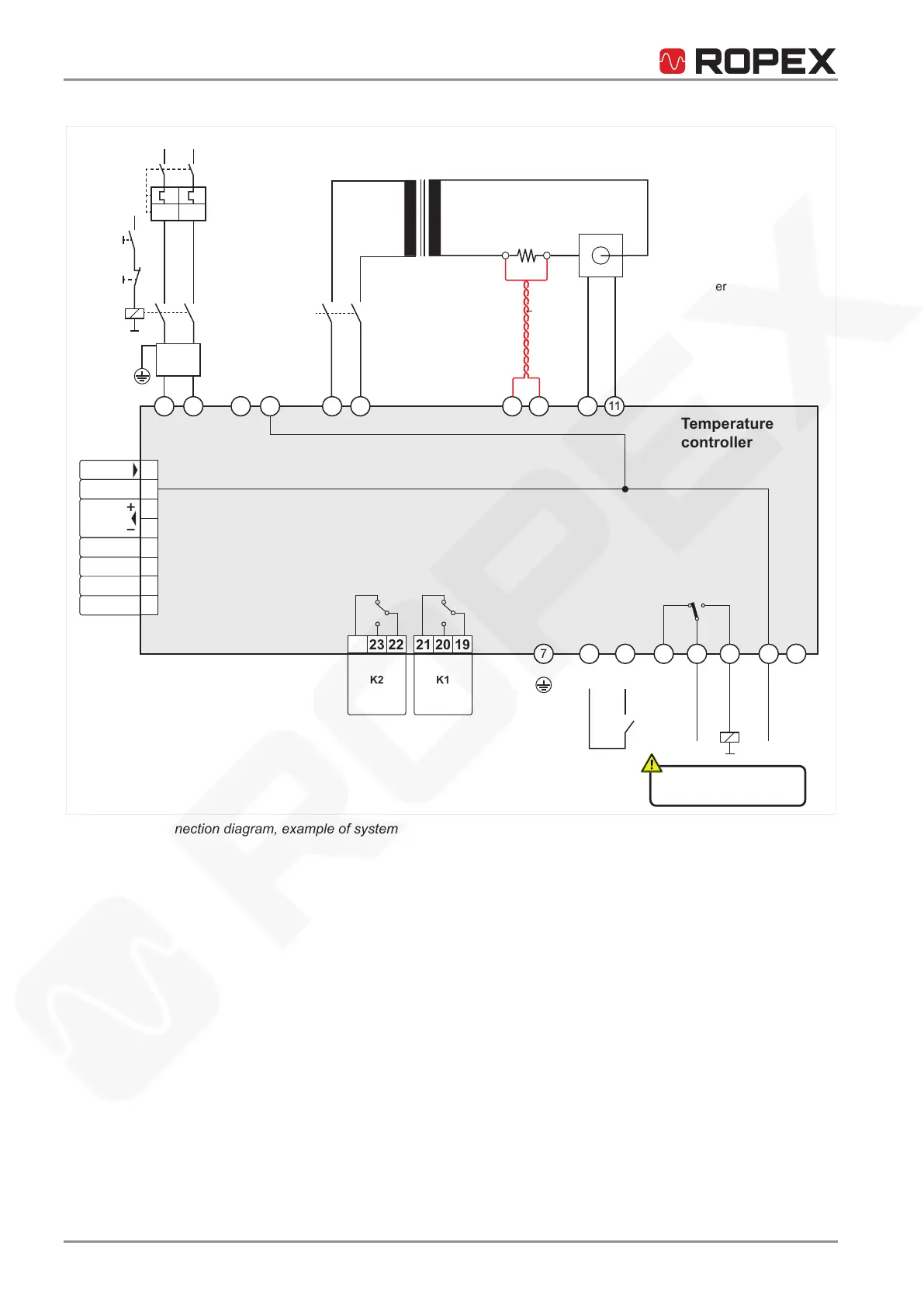
Connection diagram for system without booster
1 2 3 4 8 9 10 1115 16
7 5 6 12 13 14 18 17
PE
Uref START
24 VDC
Temperature
controller
ANALOG
OUTPUT
+0...10
VDC
Ground
Menu 405:
Alarm relay
-Inverse
ALARM
OUTPUT
max. 30 V
Ground to
discharge
electrostatic
charges!
Kb
R
U
2
sec.
U
1
prim.
U
R
I
R
NETZ
Ka
Kb
Kc
I>I>
Current transformer
Line
filter
ON
(EMER-
GENCY)
OFF
Heating element
Pulse
transformer
twist
40 39 38 37 36 35 34 33
24 23 22
21 20 19
K2
CH1
GND
O
UTPUT
A1
ANALOG IN
DETACH
AUTOCAL
RESET
K1
Illustration5: Connection diagram, example of system without booster

Table of Contents

Ropex CIRUS UPT-6400 - Page 24