Assembly and installation | 5
VERSION 1 | EN-US CIRUS
®
UPT-6400 Page 25 of 104
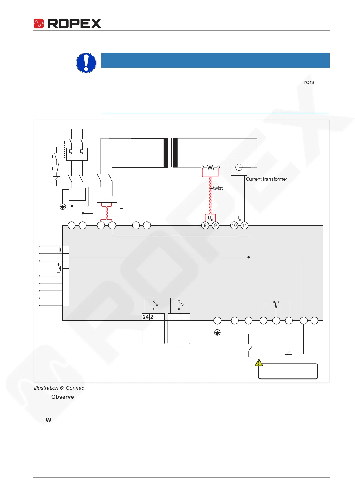
Connection diagram for system with booster
NOTICE
Electromagnetic compatibility disruption as a result of cables that are too long
If the lines to the external booster are too long or the wires are not twisted, errors can
occur when triggering the pulse transformer.
The connecting line should be no longer than 1m.
Twist the wires.
1 2 3 4 8 9 10 1115 16
7 5 6 12 13 14 18 17
R
U
R
I
R
U
2
sec.
PE
Uref
START
Kc
I>I>
24 VDC
Pulse
transformer
twist
Current transformer
Heating element
T
emperature
controller
LINE
Ground to
discharge
electrostatic
charges!
ANALOG
OUTPUT
+0...10
VDC
Ground
Menu 405:
Alarm relay
-Inverse
3
4
1 2
Ka
Kb
U
1
prim.
OUT
I
N
Booster
Kb
twist
length: max. 1 m
Line
filter
ON
(EMER-
GENCY)
OFF
40 39 38 37 36 35 34 33
CH1
GND
DETACH
AUTOCAL
RESET
OUTPUT
A1
ANALOG IN
K2 K1
24 23 22 21 20 19
ALARM
OUTPUT
max. 30 V
Illustration6: Connection diagram, example of system with booster
Observe booster
polarity
Connect the booster to terminals15+16.
- Connect booster terminal3 to the temperature controller terminal15
- Connect booster terminal4 to the temperature controller terminal16
Wiring in electrical
cabinet
An example of the layout and wiring of system components in the electrical cabinet
can be found in the appendix under .






 To Next Page