18
Reference Manual
00809-0100-4108, Rev CA
Configuration
March 2017
Configuration
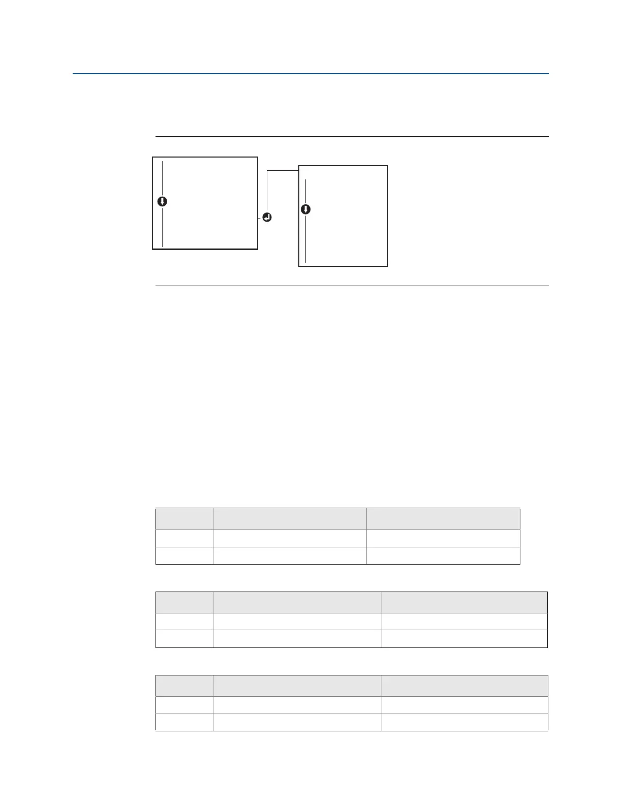
Configuring LCD display with a local operator interface
Refer to Figure 2-13 for LCD display configuration using a LOI.
Figure 2-13. Display with LOI
2.10 Detailed transmitter setup
2.10.1 Configuring alarm and saturation levels
In normal operation, the transmitter will drive the output in response to pressure from the
lower to upper saturation points. If the pressure goes outside the sensor limits, or if the
output would be beyond the saturation points, the output will be limited to the associated
saturation point.
The transmitter automatically and continuously performs self-diagnostic routines. If the
self-diagnostic routines detect a failure, the transmitter drives the output to configured
alarm and value based on the position of the alarm switch. See “Setting transmitter alarm”
on page 45.
Table 2-5. Rosemount Alarm and Saturation Values
Table 2-6. NAMUR-Compliant Alarm and Saturation Values
Table 2-7. Custom alarm and saturation values
Level 4–20 mA (1–5 Vdc) saturation 4–20 mA (1–5 Vdc alarm
Low 3.90 mA (0.97 V) ≤ 3.75 mA (0.95 V)
High 20.80 mA (5.20 V) ≥ 21.75 mA (5.40 V)
Level 4–20 mA (1–5 Vdc) saturation 4–20 mA (1–5 Vdc) alarm
Low 3.80 mA (0.95 V) ≤ 3.60 mA (0.90 V) (.90 –.95 V)
High 20.50 mA (5.13 V) ≥22.50 mA (5.63 V) (5.05 –5.75 V)
Level 4–20 mA (1–5 Vdc) saturation 4–20 mA (1–5 Vdc) alarm
Low 3.70 mA– 3.90 mA (.90 –.95 V) 3.60–3.80 mA (.90 –.95 V)
High 20.10 mA –22.90 mA (5.025 –5.725 V) 20.20 mA – 23.00 mA (5.05 –5.75 V)
DISPLAY
PRESS (on/off)
SCALED (on/off)
TEMP (on/off)
%RANGE (on/off)
ANALOG (on/off)
STRTUP (on/off)
BACK TO MENU
EXIT MENU
VIEW CONFIG
ZERO TRIM
UNITS
RERANGE
LOOP TEST
DISPLAY
DISPLAY
EXTENDED MENU
EXIT MENU