47
Reference Manual
00809-0100-4108, Rev CA
Electrical Installations
March 2017
Electrical Installations
Note
A minimum loop resistance of 250 Ωs is required to communicate with a Field
Communicator. If a single power supply is used to power more than one transmitter, the
power supply used, and circuitry common to the transmitters, should not have more that
20 Ωs of impedance at 1200 Hz.
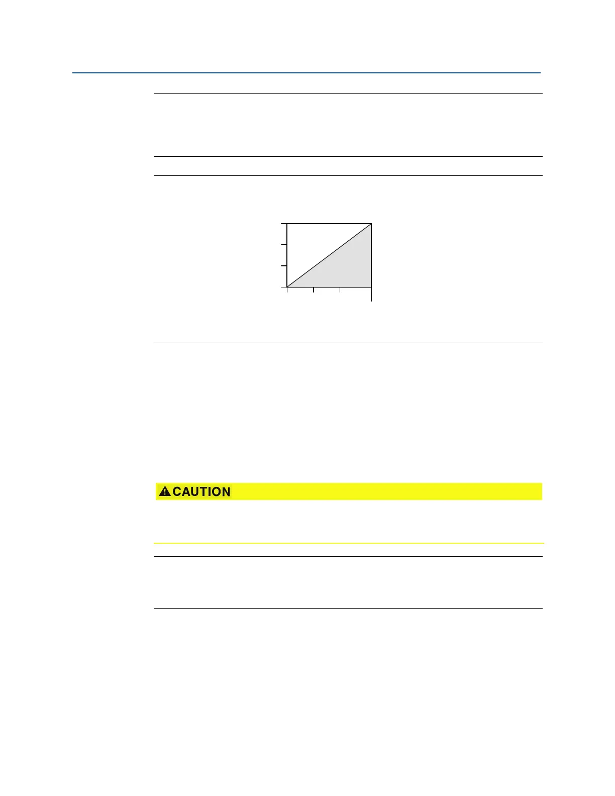
Figure 4-5. Load limitation
The total resistance load is the sum of the resistance of the signal leads and the load
resistance of the controller, indicator, I.S. Barriers, and related pieces. If intrinsic safety
barriers are used, the resistance and voltage drop must be included.
1–5 Vdc low power HART (output code N)
Low power transmitters operate on 9–28 Vdc. The dc power supply should provide power
with less than 2 percent ripple. The V
out
load should be 100 kΩ or greater.
4.6.3 Wiring the transmitter
Note
Use shielded twisted pairs to yield best results. To ensure proper communication, use 24
AWG or larger wire and do not exceed 5000 ft (1500 m). For 1–5 V 500 ft (150 m) maximum
are recommended. Unpaired three conductor or two twisted pairs is recommended.
Maximum loop resistance = 43.5 (Power supply voltage – 10.5)
The Field Communicator requires a minimum loop resistance of 250
Ω
for communication.
Do not connect the power signal wiring to the test terminals. Incorrect wiring can damage
test circuit.
V
Load (Ωs)
Operating
Region
1387
1000
500
0
10.5 20 30
42.4