Specifications and Reference Data
75
Specifications and Reference Data
March 2017
Reference Manual
00809-0100-4108, Rev CA
Load limitations
Maximum loop resistance is determined by the power
supply voltage, as described by:
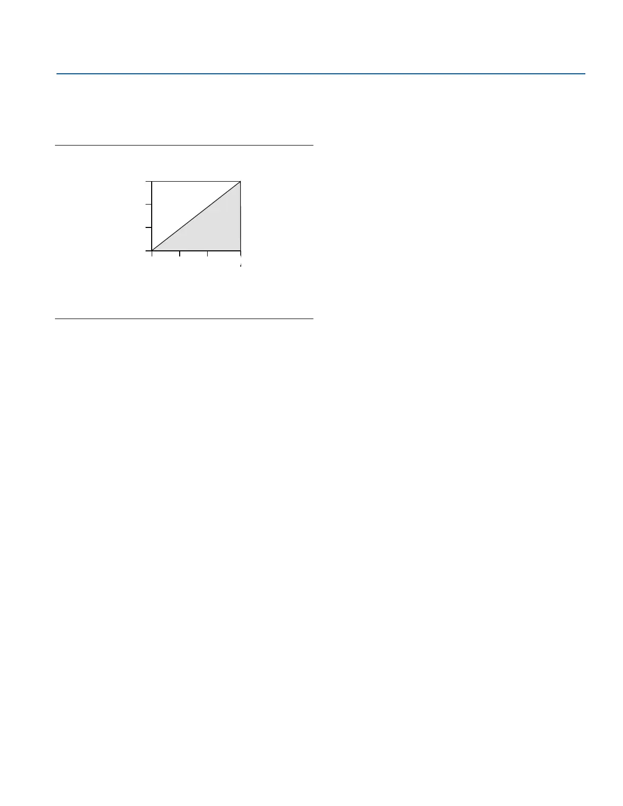
Figure A-1. Maximum Loop Resistance
Indication
Optional two-line LOI/LCD display. LOI only available with
2088.
Zero and span adjustment
requirements (HART, 2088 only)
Zero and span values can be set anywhere within the range
limits stated in the Table A-1 must be greater than or equal
to the minimum span stated in Table A-1.
Output
Digital communications based on HART Revision 5 (default)
or Revision 7 (option code HR7) protocol can be selected.
The HART revision can be switched in the field using any
HART based configuration tool or the optional local
operator interface (LOI, 2088 only).
Turn-on time
Performance within specifications less than 2.0 seconds
after power is applied to the transmitter
LOI, Rosemount 2088 only
The LOI utilizes a 2-menu display with internal and external
configuration buttons. Internal buttons are always
configured for LOI. External Buttons can be ordered and
configured as either LOI, (option code M4), Analog Zero and
Span (option code D4) or Digital Zero Trim (option code
DZ). See Appendix D: Local Operator Interface.
A.3.3 1-5 Vdc HART low power
(output code N for 2088 only)
Power supply
External power supply required. Standard transmitter
operates on 5.8 to 28 Vdc with no load.
Output
Three wire 1–5 Vdc output, user-selectable for linear or
square root output. Digital process variable superimposed
on voltage signal, available to any host conforming to the
HART protocol.
Power consumption
3.0 mA, 27-84 mW
Output load
100 k Ω or greater
Turn-on time
Performance within specifications less than 2.0 seconds
after power is applied to the transmitter.
Load (ohms)
Operating
Region
Voltage (Vdc)
Max. Loop Resistance = 43.5 (Power Supply Voltage – 10.5)
1387
1000
500
0
10.5
20 30
42.4
The Field communicator requires a minimum loop
resistance of 250
Ω
for communication.