19
Reference Manual
00809-0100-4108, Rev CA
Configuration
March 2017
Configuration
Failure mode alarm and saturation levels can be configured using a Field Communicator,
AMS Device Manager, and the LOI. The following limitations exist for custom levels:
Low alarm level must be less than the low saturation level
High alarm level must be higher than the high saturation level
Alarm and saturation levels must be separated by at least 0.1 mA (0.025 Vdc)
The configuration tool will provide an error message if the configuration rule is violated.
Note
Transmitters set to HART multidrop mode send all saturation and alarm information
digitally; saturation and alarm conditions will not affect the analog output. See also
“Establishing multidrop communication” on page 26.
Configuring alarm and saturation levels using a Field
Communicator
Configuring alarm and saturation levels with AMS Device
Manager
1. Right select on the device, and select Configure.
2. Select Configure Alarm and Saturation Levels button.
3. Follow screen prompts to configure Alarm and Saturation Levels.
Configuring alarm and saturation levels using LOI
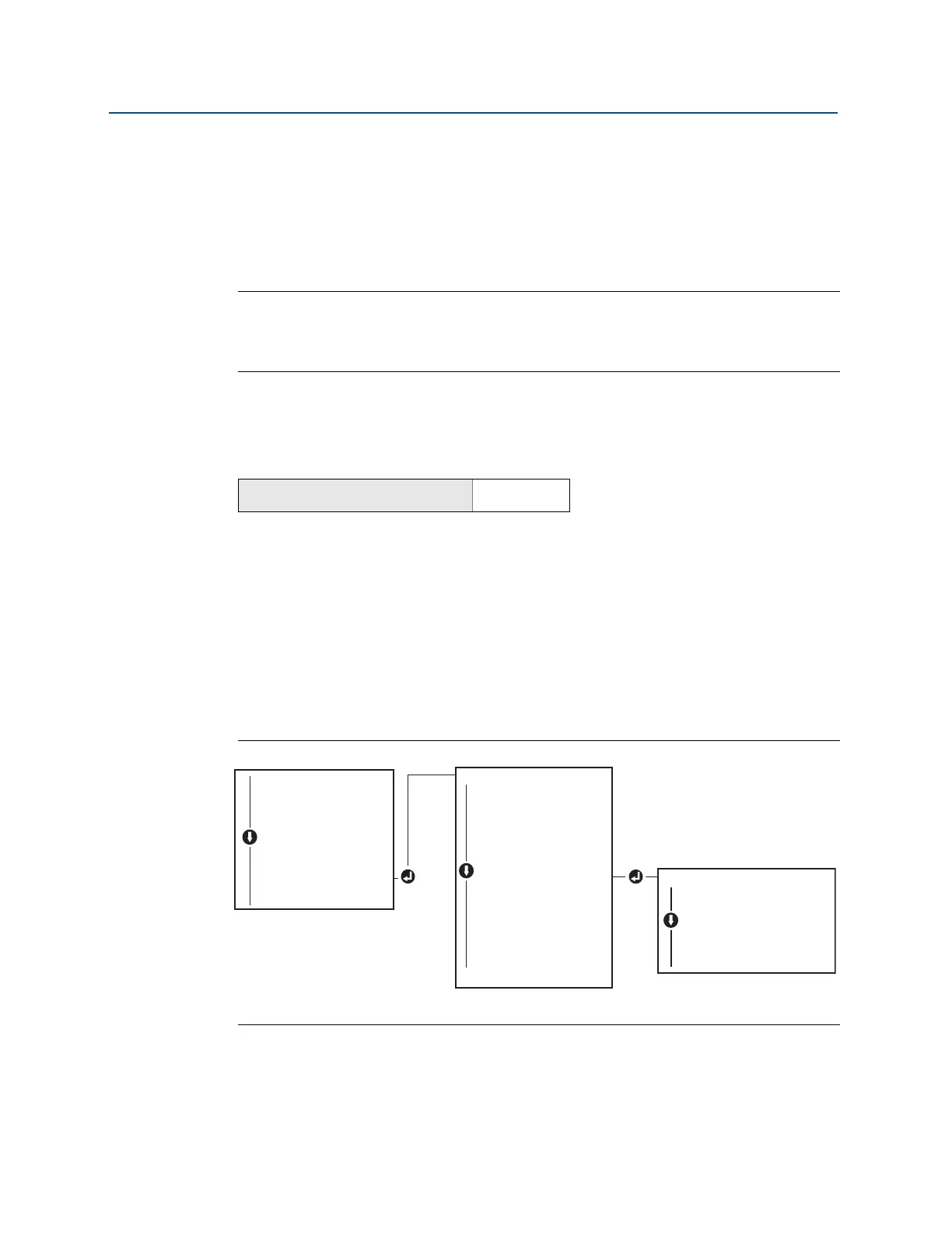
Refer to Figure 2-14 for instructions to configure alarm and saturation levels.
Figure 2-14. Configuring Alarm and Saturation with LOI
2.10.2 Configuring scaled variable
The Scaled Variable configuration allows the user to create a relationship/conversion
between the pressure units and user-defined/custom units. There are two use cases for
From the HOME screen, enter the Fast Key sequence
Device Dashboard Fast Keys
2, 2, 2, 5
EXTENDED MENU
CALIBRAT
DAMPING
TRANSFER FUNCT
SCALED VARIAB
ASSIGN PV
TAG
ALARM SAT VALUES
ALARM SAT VALUES
PASSWORD
SIMULATE
HART REV
BACK TO MENU
EXIT MENU
ALARM SAT VALUES
ROSEMOUNT VALUES
NAMUR VALUES
OTHER VALUES
BACK TO MENU
EXIT MENU
VIEW CONFIG
ZERO TRIM
UNITS
RERANGE
LOOP TEST
DISPLAY
EXTENDED MENU
EXTENDED MENU
EXIT MENU