42
Reference Manual
00809-0100-4108, Rev CA
Electrical Installations
March 2017
Electrical Installations
4.3 Local Operating Interface (LOI)/LCD display
Transmitters ordered with the LCD display option (M5) or LOI option (M4) are shipped with
the display installed. Installing the display on an existing transmitter requires a small
instrument screwdriver. Carefully align the desired display connector with the electronics
board connector. If connectors don't align, the display and electronics board are not
compatible.
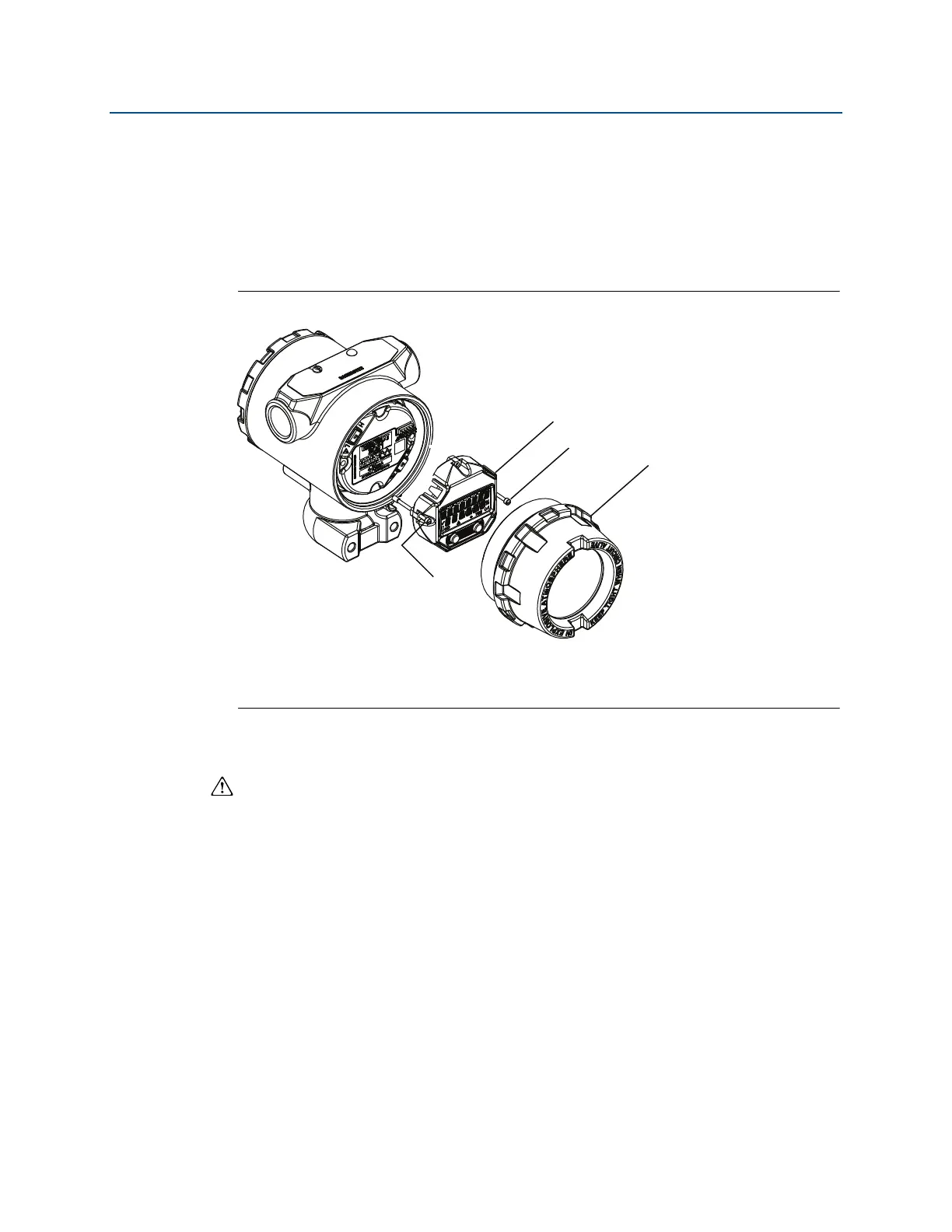
Figure 4-1. LOI display assembly
A. LCD/LOI display
B. Extended cover
C. Captive screws
4.3.1 Rotating LCD/LOI display
1. Secure the loop to manual control and remove power to transmitter.
2. Remove transmitter housing cover.
3. Remove screws form the LCD/LOI display and rotate to desired orientation.
a. Insert 10 pin connector into the display board for the correct orientation. Carefully
align pins for insertion into the output board.
4. Re-insert screws.
5. Reattach transmitter housing cover; cover must be fully engaged to comply with
explosion proof requirements.
6. Re-attach power and return loop to automatic control.
A
C
C
B