26
Reference Manual
00809-0100-4108, Rev CA
Configuration
March 2017
Configuration
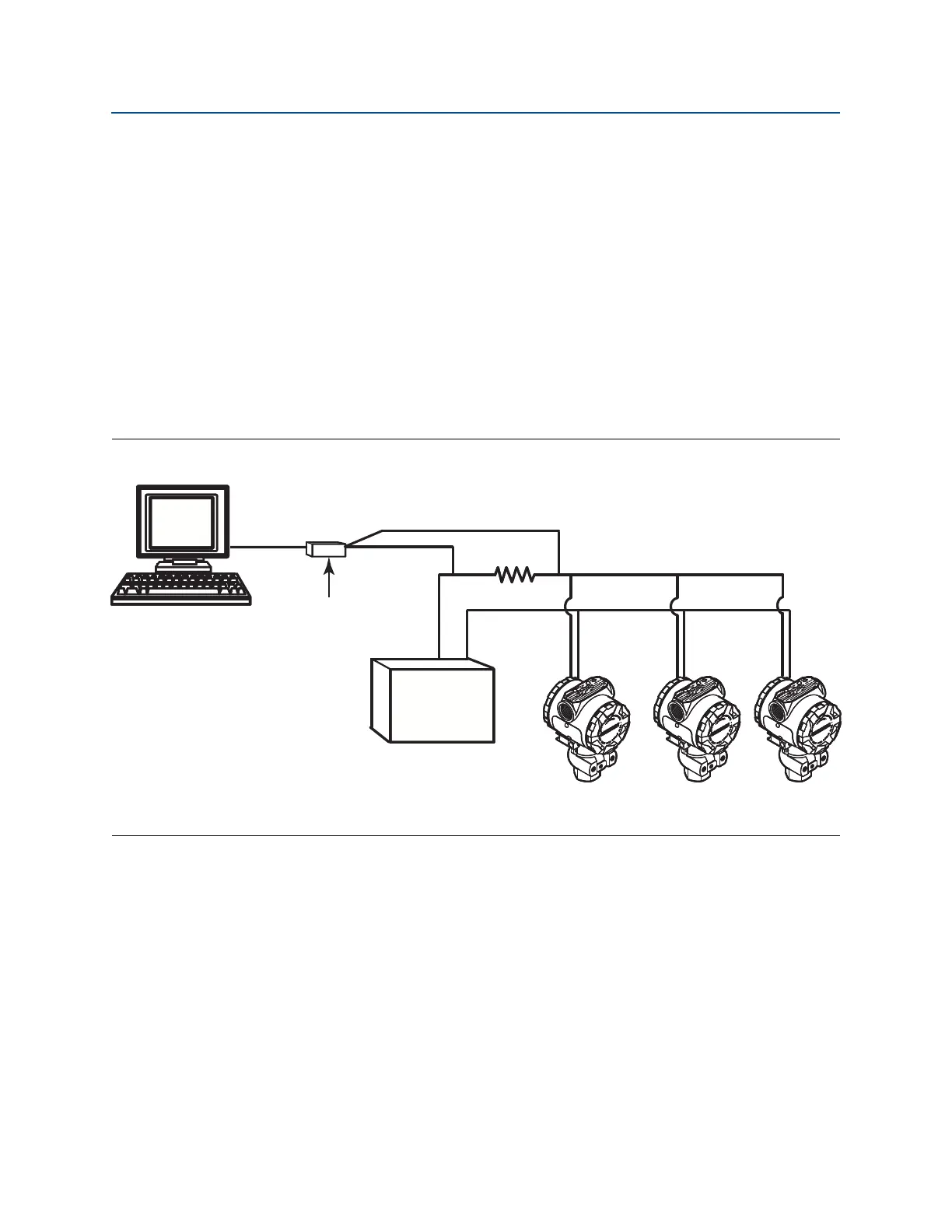
2.13 Establishing multidrop communication
Multidropping transmitters refers to the connection of several transmitters to a single
communications transmission line. Communication between the host and the transmitters
takes place digitally with the analog output of the transmitters deactivated.
Multidrop installation requires consideration of the update rate necessary from each
transmitter, the combination of transmitter models, and the length of the transmission line.
Communication with transmitters can be accomplished with HART modems and a host
implementing HART protocol. Each transmitter is identified by a unique address and
responds to the commands defined in the HART protocol. Field Communicators and AMS
Device Manager can test, configure, and format a multidropped transmitter the same way
as a transmitter in a standard point-to-point installation.
Figure 2-18 shows a typical multidrop network. This figure is not intended as an installation
diagram.
Figure 2-18. Typical Multidrop Network (4–20 mA only)
A. HART modem
B. Power supply
The Rosemount 2088, 2090F, 2090P is set to address zero (0) at the factory, which allows
operation in the standard point-to-point manner with a 4–20 mA (1–5 Vdc) output signal.
To activate multidrop communication, the transmitter address must be changed to a
number from 1 to 15 for HART Revision 5, or 1–63 for HART Revision 7. This change
deactivates the 4–20 mA (1–5 Vdc) analog output, sending it to 4 mA (1 Vdc). It also
disables the failure mode alarm signal, which is controlled by the upscale/downscale switch
position. Failure signals in multidropped transmitters are communicated through HART
messages.
2.13.1 Changing a transmitter address
To activate multidrop communication, the transmitter poll address must be assigned a
number from 1 to 15 for HART Revision 5, and 1–63 for HART Revision 7. Each transmitter in
a multidropped loop must have a unique poll address.
A
B