55
Reference Manual
00809-0100-4108, Rev CA
Operation and maintenance
March 2017
Operation and maintenance
Calibrate the sensor
Sensor trim (page 57)
Zero trim (page 59)
Calibrate the 4–20 mA output
4–20 mA/ 1–5V Output trim (page 60)
4–20 mA/ 1–5V Output trim using other scale (page 61)
5.4.1 Determining necessary sensor trims
Bench calibrations allow for calibrating the instrument for its desired range of operation.
Straight forward connections to pressure source allow for a full calibration at the planned
operating points. Exercising the Transmitter over the desired pressure range allows for
verification of the analog output. “Trim the pressure signal” on page 56 discusses how the
trim operations change the calibration. It is possible to degrade the performance of the
transmitter if a trim is done improperly or with inaccurate equipment. The transmitter can
be set back to factory settings using the “Recall factory trim—sensor trim” on page 59.
Determine the necessary trims with the following steps.
1. Apply pressure.
2. Check digital pressure, if the digital pressure does not match the applied pressure,
perform a digital trim. See “Perform a sensor trim” on page 57.
3. Check reported analog output against the live analog output. If they do not match,
perform an analog output trim. See “Performing digital-to-analog trim (4–20mA/ 1–5 V
output trim)” on page 60.
Trimming with configuration buttons
Local configuration buttons are external buttons located underneath the top tag of the
transmitter. There are two possible sets of local configuration buttons that can be ordered
with the Rosemount 2088 and used to perform trim operations: Digital zero trim and LOI.
To access the buttons, loosen screw and rotate top tag until buttons are visible.
LOI (M4): Can perform both digital Sensor Trim and the 4–20mA Output Trim (analog
output trim). Follow the same procedures listed in trimming with Field Communicator or
AMS Device Manager listed below.
Digital zero trim (DZ): Used for performing a sensor zero trim. See “Determining
calibration frequency” on page 56 for trim instructions.
All configuration changes should be monitored by a display or by measuring the loop
output.
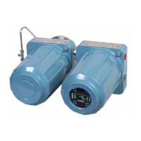
Figure 5-1 shows the physical differences between the two sets of buttons.
Figure 5-1. Local Configuration Button Options
A. LOI - green retainer
B. Digital zero trim- blue retainer