43
Reference Manual
00809-0100-4108, Rev CA
Electrical Installations
March 2017
Electrical Installations
4.4 Configuring transmitter security
There are four security methods with the Rosemount 2088, 2090F, and 2090P transmitters.
Security switch
HART
®
Lock
Configuration Buttons lock
LOI password
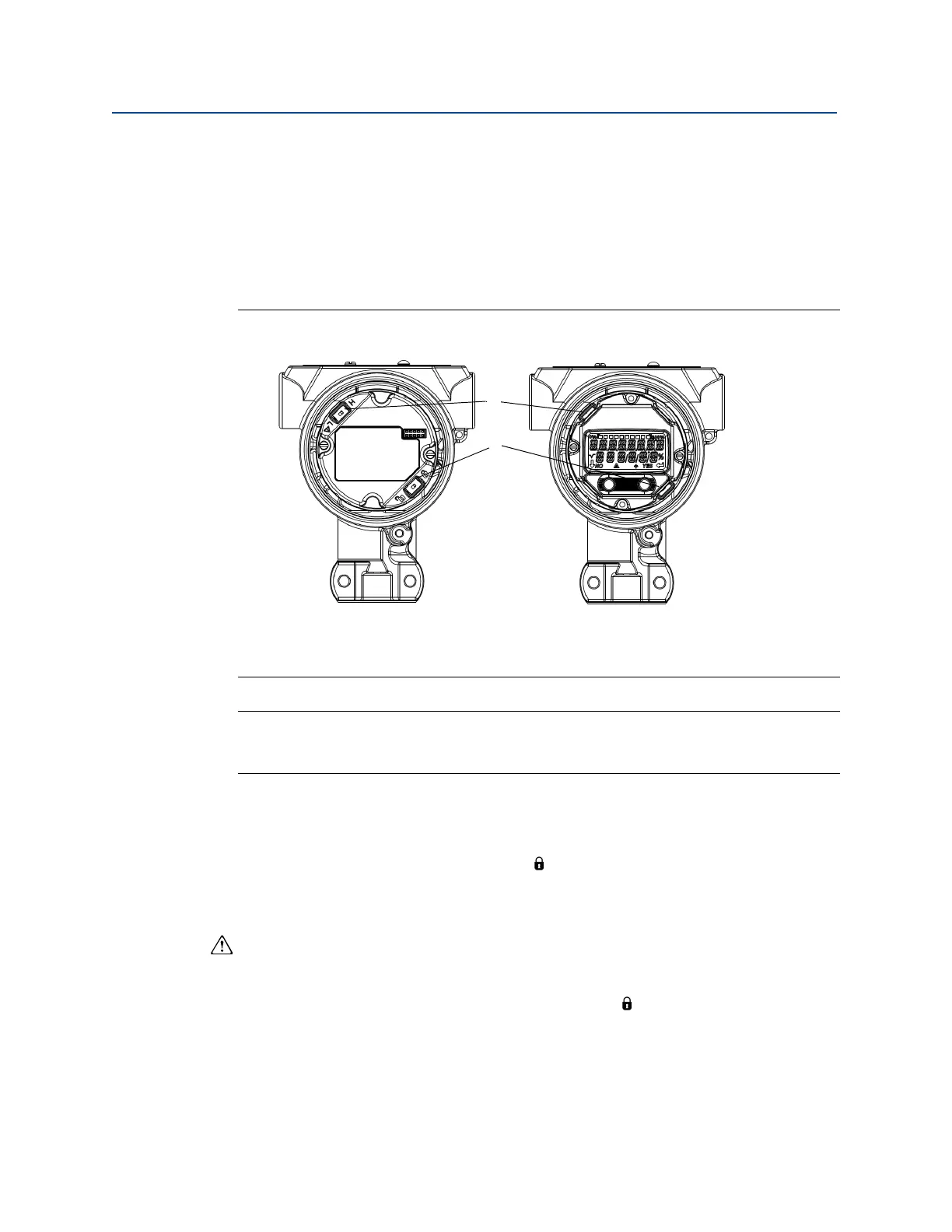
Figure 4-2. 4–20 mA electronics board
Note
1–5 Vdc Alarm and Security switches are located in the same location as 4–20 mA output
boards.
4.4.1 Setting security switch
The security switch is used to prevent changes to the transmitter configuration data. If the
security switch is set to the locked location ( ), any transmitter configuration requests
sent via HART, LOI, or local configuration buttons will be rejected by the transmitter and the
transmitter configuration data will not be modified. Reference Figure 4-2 for the location of
the security switch. Follow the steps below to enable the security switch.
1. Set loop to manual and remove power.
2. Remove transmitter housing cover.
3. Use a small screwdriver to slide the switch to the lock ( ) position.
4. Replace transmitter housing cover; cover must be fully engaged to comply with
explosion proof requirements.
Without LCD display meter With LCD display /LOI display
A. Alarm
B. Security