48
Reference Manual
00809-0100-4108, Rev CA
Electrical Installations
March 2017
Electrical Installations
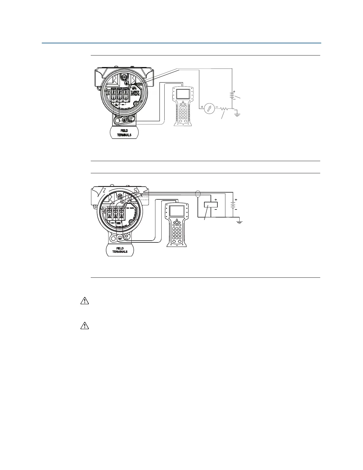
Figure 4-6. Wiring the Transmitter (4–20 mA HART)
A. DC power supply
B. R
L
≥ 250 (necessary for HART communication only)
Figure 4-7. Wiring the Transmitter (1–5 Vdc Low Power)
A. DC power supply
B. Voltmeter
Perform the following procedure to make wiring connections:
1. Remove the housing cover on terminal compartment side. Do not remove the cover in
explosive atmospheres when the circuit is live. Signal wiring supplies all power to the
transmitter.
2. For 4–20 mA HART output, connect the positive lead to the terminal marked
(pwr/comm+) and the negative lead to the terminal marked (pwr/comm–). Do not
connect the powered signal wiring to the test terminals. Power could damage the test
diode.
a. For 1–5 Vdc HART Output, connect the positive lead to (PWR +) and the negative to
the (PWR–). Do not connect the powered signal wiring to the test terminals. Power
could damage the test diode.
3. Ensure full contact with Terminal Block screw and washer. When using a direct wiring
method, wrap wire clockwise to ensure it is in place when tightening the terminal block
screw.