Specifications and Reference Data
March 2017
Reference Manual
00809-0100-4108, Rev CA
Specifications and Reference Data
80
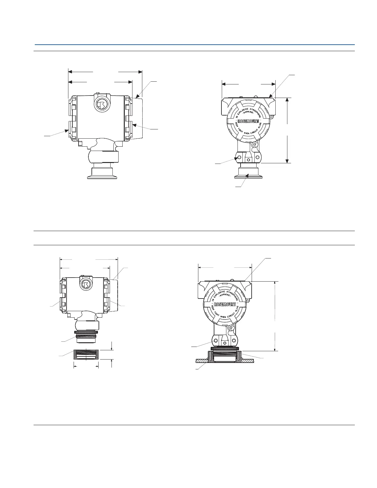
Figure A-4. Rosemount 2090F
Figure A-5. Rosemount 2090P 1
1
/2-in. Flush Mount
A. Terminal connection side
B. Optional display
C. Transmitter circuity side
Note: M20 1.5 female is also available as option.
Dimensions are in inches (millimeters).
D. 2
1
/4–20 UNC–2BX Depth 0.60 mounting holes
E. 1
1
/2- or 2-in. Tri Clamp connection
F. Certification tag
A. Weld spud
B. M44 1.25
C. Terminal connections
D. Optional display cover
E. Transmitter circuitry
Dimensions are in inches (millimeter).
F. Vessel wall
G. 2
1
/4–20 UNC–2BX depth 0.60 mounting bracket holes
H. Nameplate
I. Stress isolator groove
5.13(130)
A
B
C
4.29 (109)
A
B
C
D
E
5.13 (130)
4.29 (109) max.
0.82 (21)
2.37 (62)
F
G
H
I
3.85 (98)
4.97 (126)
Typical