DK00027.fm
REPAIR MANUAL
BRP-Powertrain
Effectivity: 125 MAX/125 Junior MAX/125 Mini
MAX/125 Micro MAX
Edition 2 / Rev. 0
Chapter 5
Page 16
December 01/2010
Graphic
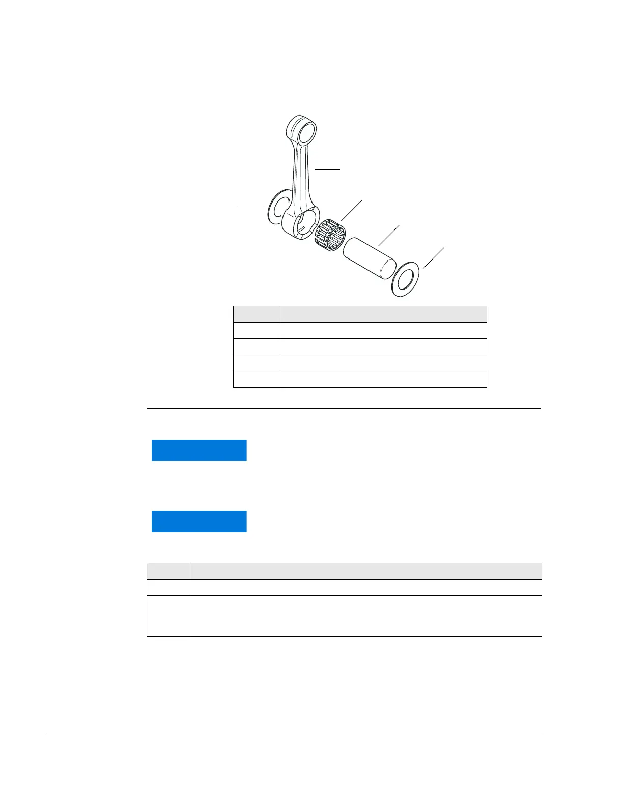
Connecting rod parts
Figure 9 K00094
Instructions See Figure 10.
Part Function
1 Connecting rod
2 Connecting rod pin
3 Needle bearing
4 Thrust washer
If the connecting rod pin is not centered on the center
hole of the bottom section of the tool (4), the
connecting rod pin, the crankshaft half and the bottom
section may be damaged.
The con rod must fit flush into the cutout in the bottom
section of the tool (4) (otherwise the connecting rod
may be damaged).
Step Procedure
1 Push thrust plate (2) between the two halves of the crankshaft.
2 Position crankshaft (3) with the thrust plate on bottom section of the tool (4)
and make sure that the connecting rod pin is above the center hold of the
bottom section.
 Loading...


