DK00025.fm
REPAIR MANUAL
BRP-Powertrain
Effectivity: 125 MAX/125 Junior MAX/125 Mini
MAX/125 Micro MAX
Edition 2 / Rev. 0
Chapter 3
Page 15
December 01/2010
3.5) Installation of the ignition system
General See Figure 8.
NOTES: On the sand-cast model the pick up for the ignition unit is
fastened to the housing with 2 M6x16 cyl. screws. On the
die-cast model the pick up for the ignition unit is fastened
to the housing with 2 M6x16 taptite screws (= self-tapping
screw).
NOTES: If the two taptite screws are installed in a previously used
housing, make sure that the screws are correctly posi-
tioned in the previously tapped threads in the housing.
Instructions Proceed as follows to install the ignition system:
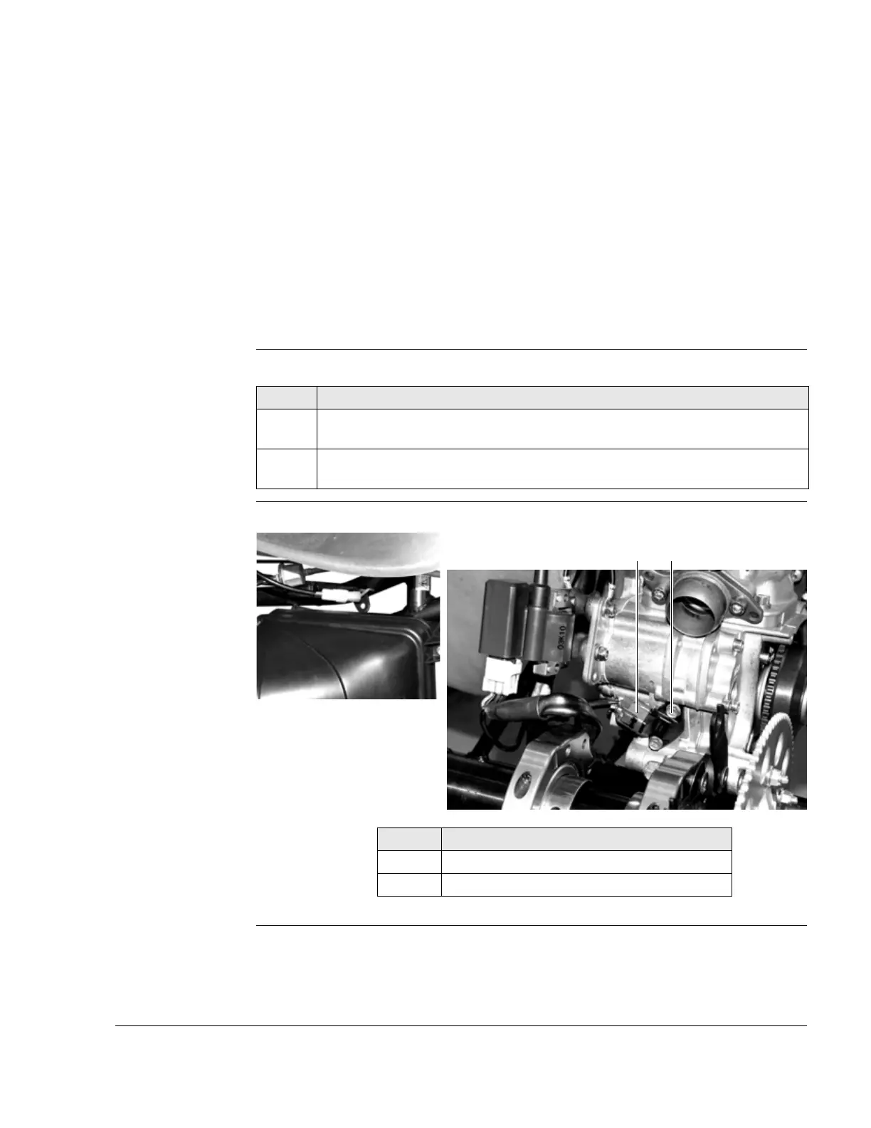
Graphic Ignition unit
Figure 8 K00131, K00130
Step Procedure
1 Position the pick up on the housing with the wiring harness terminal pointing
in the direction of the gearbox.
2 Fasten the pick up for the ignition system with the two cyl. screws or taptite
screws to the specified tightening torque of 10 Nm (90 in.lb).
Part Function
1 Pick up
2 Taptite screw or cyl. screw