DK00026.fm
REPAIR MANUAL
BRP-Powertrain
Effectivity: 125 MAX/125 Junior MAX/125 Mini
MAX/125 Micro MAX
Edition 2 / Rev. 0
Chapter 4
Page 23
December 01/2010
4) Cylinder assembly
4.1) Installation of exhaust valve (125 MAX only)
General NOTES: Make sure that the components are in their correct
positions.
Special tools The following special tools and equipment are required:
Exhaust valve See Figure 16.
Proceed as follows to install the exhaust valve:
NOTES: If the exhaust valve or the stud bolt is replaced, the stud
bolt must be secured with LOCTITE 648 in the exhaust
valve.
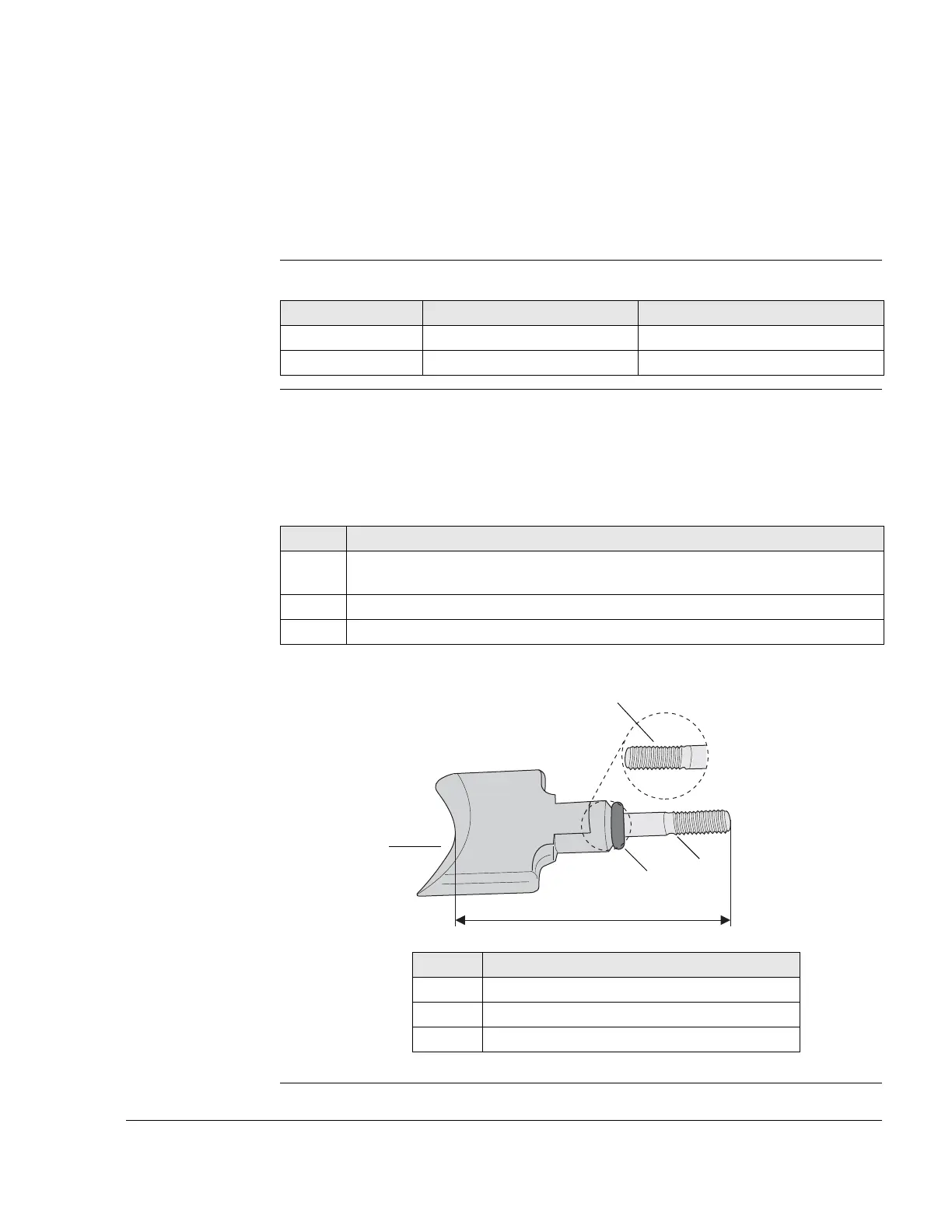
Graphic Outlet valve
Figure 16
K00155
Part number Description Use
Part no. 899788 LOCTITE 648 Stud bolt
Part no. 276070 Installation tool Valve bellows spring
Step Procedure
1 Lock exhaust valve (1) and stud bolt (2) with LOCTITE 648. Note the length
screwed in!
2 Wipe away the surplus LOCTITE.
3 Tighten O-ring 6x3.
Part Function
1 Exhaust valve
2 Stud bolt
3 O-ring 6x3