DK00027.fm
REPAIR MANUAL
BRP-Powertrain
Effectivity: 125 MAX/125 Junior MAX/125 Mini
MAX/125 Micro MAX
Edition 2 / Rev. 0
Chapter 5
Page 22
December 01/2010
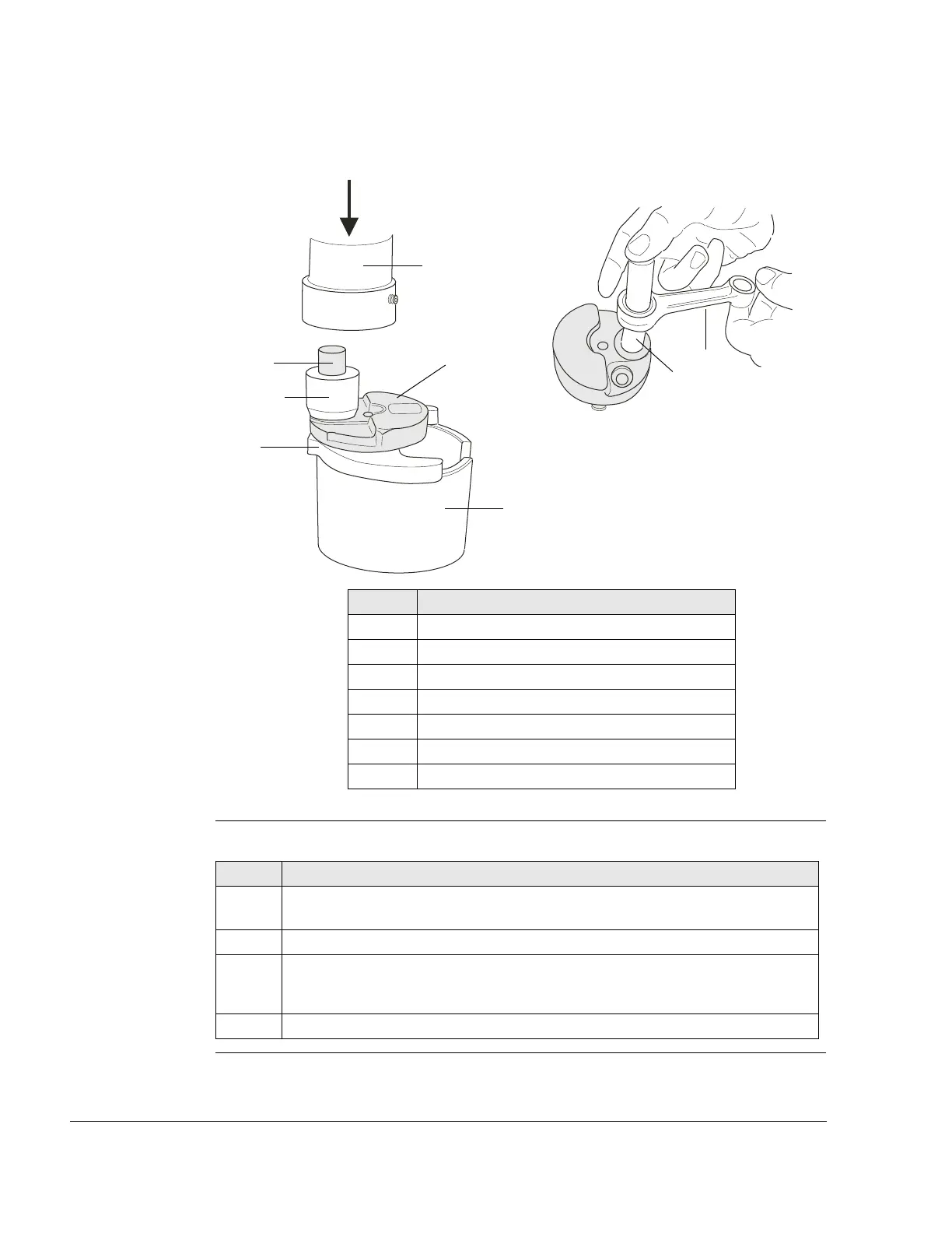
Graphic
Assembly of crankshaft
Figure 13 K00087, K00083
Instructions See Figure 14.
Part Function
1Press
2 Thrust plate
3 Drive end crankshaft half
4 Bottom section of tool
5 Connecting rod pin
6Sleeve
7 Connecting rod
Step Procedure
6 Slide the gearbox-end crankshaft half (8) into the bottom section of the
tool (4).
7 Clean the drive end crankshaft web hole with cleaning agent (grease-free).
8 Coat the hole with LOCTITE 648.
NOTES: Remove excess LOCTITE, otherwise the connecting rod
may be damaged.
9 Slide the drive-end crankshaft half (3) into the top section of the tool (9).