DK00026.fm
REPAIR MANUAL
BRP-Powertrain
Effectivity: 125 MAX/125 Junior MAX/125 Mini
MAX/125 Micro MAX
Edition 2 / Rev. 0
Chapter 4
Page 18
December 01/2010
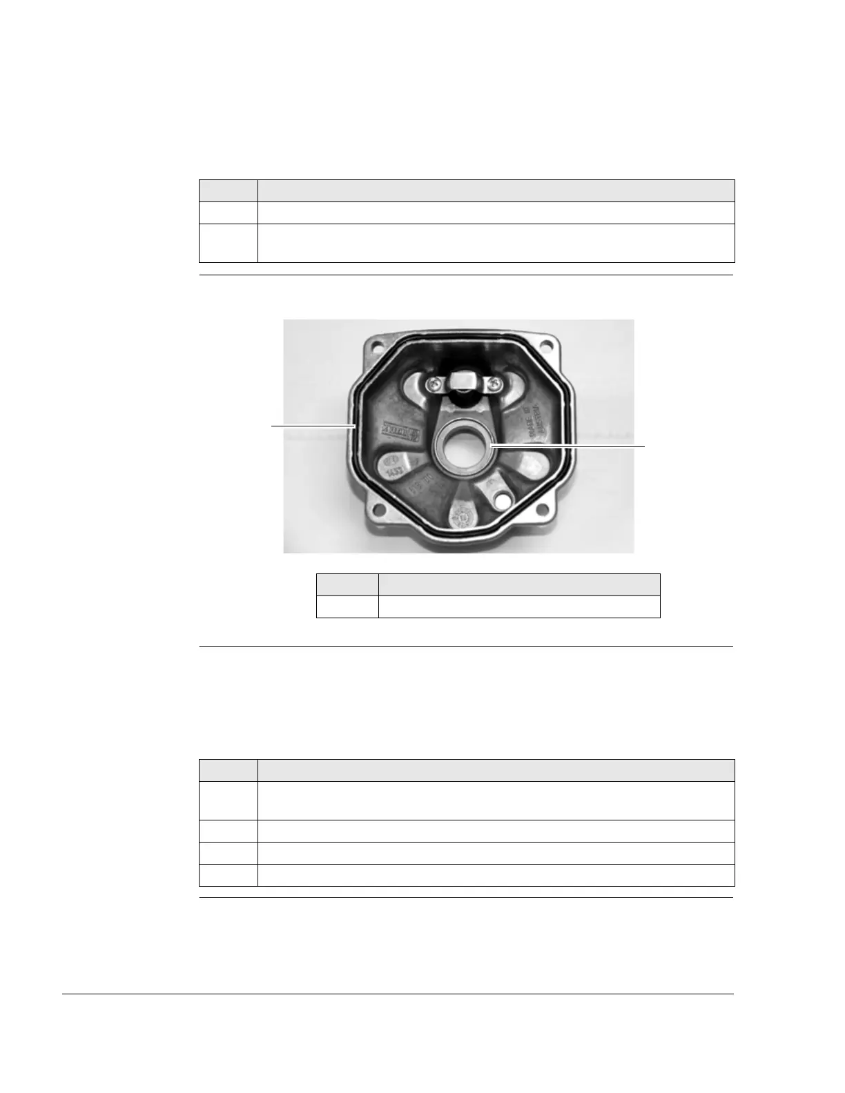
3.4) Inspection of cylinder head cover
Instructions See Figure 11.
Graphic Cylinder head cover
Figure 11 K00097
3.5) Inspection of combustion chamber insert
Instructions See Figure 12.
NOTES: The sealing area of the combustion chamber insert is
slightly tapered from
Ø 63 mm.
Step Procedure
1 Inspect cylinder head cover for cracks (visual inspection).
2 Inspect the contact surfaces of the two O-rings (1 and 2) for good condition
(max. depth of wear 0.05 mm).
Part Function
1, 2 O-ring contact area
Step Procedure
1 Clean combustion residues and lime deposits from the outer area (1) of the
combustion chamber.
2 Inspect combustion chamber insert for cracks (visual inspection).
3 Check that spark plug thread (3) is in good condition.
4 Inspect sealing surfaces for flatness and damage.
 Loading...


